Hello All,
I've been tinkering (and trying to learn along the way) with a dual voice coil driver (Boss CH10DVC). I'd like to understand the effects of shorting one of the voice coils. This, I presume creates and Eddy Current Brake like a shorting ring but let's expand on what that means for the driver in real-world use... Because I would love to know 🙂
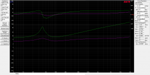
I've included two free air measurements:
Green - Both coils wired in series 8 Ohm
Magenta - Single 4 Ohm VC in use, 2nd VC shorted
Who can help me interpret these results?
Cheers!
I've been tinkering (and trying to learn along the way) with a dual voice coil driver (Boss CH10DVC). I'd like to understand the effects of shorting one of the voice coils. This, I presume creates and Eddy Current Brake like a shorting ring but let's expand on what that means for the driver in real-world use... Because I would love to know 🙂
I've included two free air measurements:
Green - Both coils wired in series 8 Ohm
Magenta - Single 4 Ohm VC in use, 2nd VC shorted
Who can help me interpret these results?
Cheers!
Attachments
Very interesting. Old timers might remember when meters arrived with their terminals shorted to keep the moving coil from swinging around (even though nominally balanced).
The shorted curve looks a whole lot better, eh. That's because you are using motional feedback or at least passive degenerative feedback (pretty much the same thing).
Like true active motional feedback, effectiveness depends on the absence of correlation of the two coils and on the inherent linearity of the magnet system (which ought to be pretty linear). It does correct for the inept way Rice-Kellogg drivers are suspended with a weird piece of rubber and some phenolic cloth (as opposed to some intelligent kind of sensible linear Boyle's Law mechanism).
Little of this will make much sense to those who think everything you need to know about drivers is enclosed in the little world of Olsen/Thiele.
Ben
You simply changed the driver Q. You can fix a potentiometer to the non-powered coil and adjust this effect. I found a document that explains this from a couple of decades (from Adire). See:
http://www.diy-audio.narod.ru/litr/RDOOperation.pdf
I also found this doc, that might be helpful:
Dual-VC
http://www.diy-audio.narod.ru/litr/RDOOperation.pdf
I also found this doc, that might be helpful:
Dual-VC
Last edited:
Yes, you damped the speaker a lot with an eddy current brake.
The shorted coil also strongly attenuated the residual inductance which rises impedance at higher frequencies.
I bet the effect at lower frequencies is even stronger than a plain shorting ring, because the latter is static and only attenuates by magnetic coupling while the shorted coil not only shorts the magnetic field but also acts as a generator driving a shorted load (the shorting ring does not do that) so at least conceptually the braking effect must be stronger.
FWIW after hating aluminum former coils for ages , preferring non conductive formers, now I'm reconciling myself with them, seeing that they require a different approach but can do their own thing.
Personally I don't lightly despise Olsen/Beranek/Thiele/Davis and other old timers, every time I read them I find something "new" and useful, go figure.
Kapton/Nomex/Kevlar/fiberglass/carbon fiber/epoxy/neodymium/etc. are new *materials* they didn't even dream of, but the Physics Laws remain the same 😉
... least passive degenerative feedback
Hate it when that happens, but there have been times I deserved it.
Basically the shorted coil increases the effective mechanical damping. The reduced Qms results in a really small impedance peak. The shorted coil acting like copper cladding or shorting rings in the magnetic circuit is an added bonus, but I haven't tried to predict that part 😉
We all agree. Wonderful.
And while it (or shorting rings or much else) really isn't in the Olson model, nobody doubts it can be portrayed in the electrical-analogy model (perhaps as simply as doing something imaginative to Qes).
But now the real question: does it improve the driver's performance? Seems to me, any reasonably linear negative feedback has to help. The charts show the expected reduction in resonance (or Q perhaps) and the improvement in phase error. Does this help the sound?
BTW, would it be true to say the sim advocates have no way to evaluate the question and particularly matters of transient performance?
Ben
BTW, would it be true to say the sim advocates have no way to evaluate the question and particularly matters of transient performance?
To call an electromagnetic dissipating force "feedback" is a stretch. As far as evaluating transient response, small-signal will closely follow T/S theory, and large signal will need a much more complicated nonlinear model - or (simpler) measurement.
Will it improve sound? I doubt it. If you really need the flat impedance, it could be useful, but getting a driver that already has copper in the motor is a better solution. It throws away a coil that could be generating output so you lose 6dB of voltage sensitivity. The system damping it provides could be accomplished another way, like DSP.
Interesting indeed. From what I can tell, the upside to this configuration would be a drop in Le and a smaller deviation is phase near Fs frequencies. The downside being reduced power handling and sensitivity. Considering that this is a subwoofer and the effects of Le at low frequencies are unclear to me, I may have to run some more tests and let my ears weigh in. Thanks for the information guys.
We all agree. Wonderful.
I don't want to speak for anyone but I don't think anyone has actually agreed with the premise that this shorted coil actually improves the driver.
And while it (or shorting rings or much else) really isn't in the Olson model, nobody doubts it can be portrayed in the electrical-analogy model (perhaps as simply as doing something imaginative to Qes).
But now the real question: does it improve the driver's performance? Seems to me, any reasonably linear negative feedback has to help. The charts show the expected reduction in resonance (or Q perhaps) and the improvement in phase error. Does this help the sound?
This is exactly why your premise is wrong. Reducing the impedance peak has no practical benefit. And phase is not an error.
If you view the impedance peak and it's resulting phase as bad then everything that follows will be based on a misunderstanding of what these things are, what they mean and what effect they have.
You've spoken out in the past about the "dangers" of operating below fs, it's clear that you don't really understand how these things work.
BTW, would it be true to say the sim advocates have no way to evaluate the question and particularly matters of transient performance?
Ben
I'd say sim advocates are in a much better position to evaluate the effects than you are.
By shorting the coil you have:
1. Decreased the sensitivity of the driver. Subwoofer drivers usually already have very low sensitivity.
2. Decreased the power handling.
3. Decreased the qts.
And you've decreased the sensitivity, qts and power handling a LOT, not just a bit.
So what effect does all that have?
First, you need a bigger box for any given goal qtc, and in fact if qts is too high even an infinite sized box might not get you into a reasonable qtc range. But if you have eq you can have any qtc you want.
Second, the decreased sensitivity AND decreased power handling. The reduced sensitivity means you have to put a LOT more power through the one operating coil to achieve the same spl. And the decreased power handling means the one operational coil can only handle some fraction of the driver's intended power handling. Combined, this means the driver will be severely limited in terms of max spl.
Because of that you will run into power compression issues very early on at low spl.
So what does the shorted coil ACTUALLY accomplish? You've squashed the impedance peak and the resulting phase. Neither of those were a problem in the first place. And you've reduced the inductive rise at high frequencies. This is basically meaningless for a subwoofer as it isn't interested in high frequencies anyways.
In exchange you've absolutely ruined the driver's performance by dramatically increasing qts (by 2x or more), dramatically decreasing sensitivity and dramatically decreasing power handling. These things are more likely to INCREASE distortion and REDUCE performance at moderate to high power levels and there's no real benefit at all.
They only real benefit the Adire paper alludes to is the ability to change the q (the sound) on the fly, with a more "musical" q and a "thicker" q. It would be a LOT better to do this with eq because if the driver is not a super low qts driver in the first place, you will never be able to achieve the low "musical" q even in an infinite size box, and the other cons to doing this (decreased sensitivity and power handling) significantly decrease the performance potential of the driver and will result in higher distortion at moderate to high power levels. Basically a lose/lose situation.
Let's look at the logical extension of your premise. Some drivers have quad voice coils. So if shorting one voice coil is good, shorting 3 voice has to be better, right? The impedance peak at fs will be virtually non existent and the phase would be almost a flat line. Super cool, no?
No, not super cool, absolutely not.
The gap has to be necessarily large to accommodate the 4 coils. That alone is bad for sensitivity.
Now with 3 shorted coils qts shoots through the roof. It's several times higher than if you wired all the voice coils to be active. There's now no sealed box size (including infinite) that can bring qtc into a reasonable range.
With 3 shorted coils the sensitivity is several times lower than it would be with all coils wired active. Do I need to explain why that is bad?
With 3 shorted coils power handling is a small fraction of what it would be if all coils were wired active. Again, very bad.
So now you have a situation where you have a very wide gap, very high Mms and very little of the motor force is being used by the one active coil. Qts is absurdly high, sensitivity and power handling are absurdly low. This driver is effectively a paper weight, it's completely useless.
But the impedance peak is almost non existent and the phase is almost a flat line, isn't that good?
NO.
This constant assault and vendetta against resonance in the enclosure and in the driver itself is nonsensical. You simply don't understand how any of this stuff works and prove it with almost every post you make.
But now the real question: does it improve the driver's performance? Seems to me, any reasonably linear negative feedback has to help. The charts show the expected reduction in resonance (or Q perhaps) and the improvement in phase error. Does this help the sound?
BTW, would it be true to say the sim advocates have no way to evaluate the question and particularly matters of transient performance?
Ben
Walk out to your barn, hitch up two of your strongest mules to your wagon and go for a ride. During your trip imagine that one of your mules may be sufficient to pull your wagon, so climb down off the wagon and hobble one of the mules. Resume your trip.
This is a real time test with very real consequences. Note them all, positive and negative, including all measurable efficiency losses and transient losses as your wagon struggles along its path, going up (and down) moderate grades. Note also the increased effort it takes to get your wagon rolling and to get it stopped, even to steer its direction on the lane. Note the sudden increase of sweat on your working mule now being pushed to its limits by this parasitic experiment. Stop this abusive experiment now, or risk killing your strong mule.
Wouldn't it be safer and more humane to simulate your imaginative hypothesis than to harm your strong mule in a real time test? You can ben, in any number of correlative simulations. Walk to your gasoline fueled car (or use your neighbor's car, better yet!) and open the hood. Remove one or more spark plug wires from the motor and take it for a spin. Note this introduction of parasitic loss in the efficiency and performance of the motor and their consequences now realized by the car.
Want a closer, more accurate simulation model to measure the effects of introduced parasitic losses on your mule team? Use a simulation tool that is designed and optimized for the job! You can do this yourself.
You have been repeating over and over here in various threads that simulations do not/cannot correlate accurately to real consequences. You seem to be inferring that there is some as yet unidentified black magic going on with loudspeakers and their various alignments that cannot be known (or shown through testing) by us lowly humans, yet somehow you have a clue to the origin(s) of this privileged information.
The human mind performs the same tasks in the same manner in delusion as it performs in reality, some times even coming to same conclusions due to lack of understanding! This is why we humans must test.
Real consequences must be learned while our delusions must be identified and corrected ben. Else countless mules will continue to be abused. Have no fear of testing tools, empower your mind with them.
Wow…this thread kinda went off in the weeds. 
But it’s an interesting modeling challenge and not discussed often, so figured I might as well post some info taken from my notes on past DVC investigation.
Surprisingly, a lumped parameter model for DVC woofers with individual VC inputs is not easy to find, if at all. A bit of reading (Olson, Beranek, etc) and it is easy enough to work it out for yourself. I can post if anybody is interested, but perhaps a few response trends would be more enlightening than a circuit diagram.
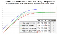
Attachment #1: Comparison of responses for different DVC configurations ignoring VC inductance
- Ignoring Le for the "first look" improves clarity with regards to damping and sensitivity changes.
- Series connection of VCs results in identical frequency response to parallel connection, but -6dB SPL reference level. If input voltage is doubled, the SPL and power dissipation would be the same as for the parallel connection.
- Driving a single VC with the other VC shorted results in the same frequency response and SPL reference level as the series connection, but requires twice the power dissipation.
- When driving a single VC, note that Qts for the open VC2 case is the same as Qms for the shorted VC2 case. This is not a coincidence. In both cases, the electrical damping from one VC is being lumped together with the mechanical damping. Whether parallel, series, or shorted VC configuration is used...once you get electrical damping from both VCs combined with the mechanical damping you wind up with the same Qts. In the lumped model all damping resistances are in parallel. It’s just a matter of T/S parameter book keeping whether electrical damping from one of the VCs gets combined with the other VC damping(Qes for the series and parallel configs), or the mechanical damping(Qms for shorted VC config).
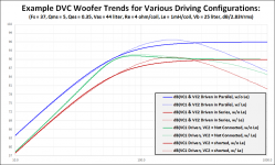
Attachment #2: Comparison of response for DVC configurations with and without VC inductance.
- All observations for Attachment #1 above still apply.
- No change to high frequency response with shorted VC compared to series/parallel configurations.

I'd include Baxandall in that list as well.
But it’s an interesting modeling challenge and not discussed often, so figured I might as well post some info taken from my notes on past DVC investigation.
Surprisingly, a lumped parameter model for DVC woofers with individual VC inputs is not easy to find, if at all. A bit of reading (Olson, Beranek, etc) and it is easy enough to work it out for yourself. I can post if anybody is interested, but perhaps a few response trends would be more enlightening than a circuit diagram.
Attachment #1: Comparison of responses for different DVC configurations ignoring VC inductance
- Ignoring Le for the "first look" improves clarity with regards to damping and sensitivity changes.
- Series connection of VCs results in identical frequency response to parallel connection, but -6dB SPL reference level. If input voltage is doubled, the SPL and power dissipation would be the same as for the parallel connection.
- Driving a single VC with the other VC shorted results in the same frequency response and SPL reference level as the series connection, but requires twice the power dissipation.
- When driving a single VC, note that Qts for the open VC2 case is the same as Qms for the shorted VC2 case. This is not a coincidence. In both cases, the electrical damping from one VC is being lumped together with the mechanical damping. Whether parallel, series, or shorted VC configuration is used...once you get electrical damping from both VCs combined with the mechanical damping you wind up with the same Qts. In the lumped model all damping resistances are in parallel. It’s just a matter of T/S parameter book keeping whether electrical damping from one of the VCs gets combined with the other VC damping(Qes for the series and parallel configs), or the mechanical damping(Qms for shorted VC config).
Attachment #2: Comparison of response for DVC configurations with and without VC inductance.
- All observations for Attachment #1 above still apply.
- No change to high frequency response with shorted VC compared to series/parallel configurations.
+1Personally I don't lightly despise Olsen/Beranek/Thiele/Davis and other old timers, every time I read them I find something "new" and useful
I'd include Baxandall in that list as well.
Attachments
- Status
- Not open for further replies.
- Home
- Loudspeakers
- Subwoofers
- Dual Voice Coil as Eddy Current Brake