
The switch is the best solution, but there is a alternative: a passive mixer. They are readily available with 3.5 jack connectors for use with small class-D amplifiers, the most common one does have a star shape and is sold at low cost on major online retailers. Passive mixers with RCA inputs are less common and way more expensive, it is best to build it yourself.I would like to connect two sources (tuner, CD player) to the input on a small tube amp. Can I just hardwire both sources and turn each on and use as needed or do I have to have a switch for some reason to select between sources?
The circuit is very simple: just a resistor in series between each RCA input and the output. 10K is a common value. The purpose of the resistor is to avoid a fight between the output buffers of the sources. It also overcomes the attenuation that may arise when a source is turned off.
TonyEE, thank you for your answer and explanation. That’s exactly what I was looking for; very helpful. And now, if someone googles my question-> there is the answer.
I’m just learning electronics so I apologize that this was too basic for some.
The astonishing thing I find in forums is that no one is holding a gun to anyone’s head to post a response so why do experienced people feel the need to complain and ridicule inexperienced people? I mean, if we all had the answers then what is the point of a forum? And if someone is that awesome why are they so insecure that they need to let everyone know how awesome they are? And if someone is so troubled by a trivial question, guess what… there’s a little “x” that lets you close the page and move on with your life.
Sorry GM but that article explains how to connect 2 amplifiers together, which was not asked.3 Best Ways to Connect 2 Amplifiers Together – Easy Steps Source
For future reference: I just copied/googled your Q and this was the first site. BTW I find most things I now no longer remember this way
This should have been mentioned in the first post.I would like to connect two sources (tuner, CD player) to the input on a small tube amp.
Connectors by themselves "do nothing", you may connect 10 RCAs in parallel if you wish, the point is whether you connect multiple sources simultaneously or not.
As of:
your answer should have stopped there.Yes it would be best to add a switch and a second set of RCA connectors.
But you had to add:
and you opened Pandora´s box 🙂Please think of what the results can be of connecting 2 sources outputs in parallel.
Same mistake 😉can you guess what will happen?
Specially from the one turned OFF 😉joining them together will result in one shorting out the other resulting in very low level on both of them.
I bet you missed: "hardwire both sources and turn each on and use as needed"
As of buying a passive mixer, extra cables, etc, it´s not needed.
If the OP is doing the effort to drill a chassis and mount an extra pair of RCA connectors, adding 4 resistors joining them is easy peasy.
And that would allow him to do what he wanted: leave both connected and just turn ON one or the other.
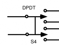
Still that will be worse than a simple DPDT source selector switch (assuming good audio/technical performance/ergonomical results are desired). Why?
That switch also will prevent possible simultaneously playing sources. The switch will also prevent DC coupled output stages with DC servos to go crazy when they are paralleled. Just 2 RCA connectors and a DPDT switch will make an almost perfect solution as it is either input 1 or input 2. OP can leave both sources connected (as usual, no serious dude pulls cables) and just selects Source 1 or Source 2 with the switch. Like most audio amplifiers are operated for a few decades.
For best results combined with least wiring it is advisable to keep signals close to the connectors instead of routing them to the front (switch). I use small relay PCBs for this and then an elegant mini switch can be used on the front of the amplifier.
Last edited:
You make a lot of good points, and I understand how it looks from your side.TonyEE, thank you for your answer and explanation. That’s exactly what I was looking for; very helpful. And now, if someone googles my question-> there is the answer.
I’m just learning electronics so I apologize that this was too basic for some.
The astonishing thing I find in forums is that no one is holding a gun to anyone’s head to post a response so why do experienced people feel the need to complain and ridicule inexperienced people? I mean, if we all had the answers then what is the point of a forum? And if someone is that awesome why are they so insecure that they need to let everyone know how awesome they are? And if someone is so troubled by a trivial question, guess what… there’s a little “x” that lets you close the page and move on with your life.
But there is also often the feeling that someone asks a simple question without first putting in an effort to find the answer themselves.
I think that is what often ticks people off here, 'why should I put in some of my rare spare time if the questioner doesn't?'
Not saying this is the case with you. But if an answer is up for grabs, nobody learns anything and the simple (silly?) questions continue.
Jan
I used a 'mixer' schematic, with a virtual zero sum point. It works well enough, but has quite a large power transient on power-up and power-down. Eventually I abandoned it out of the irritating thump.
For a different application, I've also made a small 'auto-switcher' with some 5V signal relays and the USB power from respective sources (all of them had such a port). This allows for automatic input switching.
From a purist point of view, the mixer is always putting those pots in the path of the signal.... even if they say the go to 0 impedance... I still don't believe it.
A switch is, IMHO, the second best. So is a passive preamp (except when it's volume control is executed with discrete steps.. but then you're back to a switch).
A good sounding active preamplifier is likely the best for the vast majority of people, including yours truly.
The best, but most inconvenient, is to reach out back and plug/unplug your components by hand. At that point, however, you will have to deal with the volume. Hmm.... some of my amps have gain adjustments.... the NAD monitor amps have them on the front panel, and with separate L/R they also implement a very nice balance control, so they are very convenient, but I got better sounding amps...
Lol, yep, I’m at a point where my gear is finally good enough that I can hear every component. I added a Schiit SYS and noticed the decline in SQ so I think I might just give it the reach around and unplug/plug the device I need and bypass the switch.From a purist point of view, the mixer is always putting those pots in the path of the signal.... even if they say the go to 0 impedance... I still don't believe it.
A switch is, IMHO, the second best. So is a passive preamp (except when it's volume control is executed with discrete steps.. but then you're back to a switch).
A good sounding active preamplifier is likely the best for the vast majority of people, including yours truly.
The best, but most inconvenient, is to reach out back and plug/unplug your components by hand. At that point, however, you will have to deal with the volume. Hmm.... some of my amps have gain adjustments.... the NAD monitor amps have them on the front panel, and with separate L/R they also implement a very nice balance control, so they are very convenient, but I got better sounding amps...
No pots were harmed in the making of that device. Just the virtual zero circuit. This eliminates the need for any switching, as long as the source can drive the lowish input impedance. I used a 4k7 input resistor, and faced no issues. Apart from the aforementioned thump.From a purist point of view, the mixer is always putting those pots in the path of the signal.... even if they say the go to 0 impedance... I still don't believe it.
I'd add that a mechanical switch contact isn't exactly a piece of wire either, and quality can vary quite wildly. Using the switch to activate a signal relay of reasonable quality is probably a better approach, IMO.
No pots were harmed in the making of that device. Just the virtual zero circuit. This eliminates the need for any switching, as long as the source can drive the lowish input impedance. I used a 4k7 input resistor, and faced no issues. Apart from the aforementioned thump.
I'd add that a mechanical switch contact isn't exactly a piece of wire either, and quality can vary quite wildly. Using the switch to activate a signal relay of reasonable quality is probably a better approach, IMO.
Actually, some big jumpers? Or terminate the inputs into some big banana female posts and then use some kind of a jumper? Like an old phone switchboard...
Handle the volume the same way?
And just to tweak the crowd... put a RED LED on it. Why? Well, surely you will need a 48VDC to "warm up" and "align" the mono crystals in the jumpers. When not in use, the jumpers should be plugged across a couple of 48 VDC ( and GND ) posts with a 1Mohm to ground.
Make sure to use the Signature Mk III versions of whatever teflon pseudo Viking crystal wires you've selected.
Of course, some folks will swear that spades have a wider soundstage then bananas...
Last edited:
Yea, and cryo everything right?
It depends on whether you're using a metric or fahrenheit scale when running the cryogenic system.
The English scale has far more of that desirable cubit per forthnight harmonic scales, while the metric does a better logarithmic chromatic tone.
Maybe something from here...
https://www.diyaudio.com/community/threads/developing-a-2a3-set.389161/
Gotta go... my Tice clock needs new batteries and I have to make sure they are at precisely 57% of capacity.
That's a little snarky, don't you think? Omron has a detailed study on contact degradation.
Mechanical contact switches degrade with time and contact with oxygen and moisture. Contact reliability is generally fairly poor over time, specially due to the lack of wetting current. For applications with low criticality, it probably doesn't matter. A signal relay is a cheap, simple way to ensure you have generally repeatable performance over thousands of cycles, and don't suffer from oxidation.
This is especially important where the switching current is too low to help clean the contact, as is common when using industrial-grade switches to toggle low-level signals. Such is also seen when using general purpose relays to switch speaker outputs. Since there is no DC, you do not get the arcing needed to clean the (usually silver-based) contact. The contact material needs to be different in such cases.
You can read more about this phenomenon here:
https://electronics.stackexchange.c...mmended-voltage-current-for-dry-contact-input
If you prefer lighter reading, here's a good reference:
https://en.wikipedia.org/wiki/Wetting_current
That's a little snarky, don't you think? Omron has a detailed study on contact degradation.
Mechanical contact switches degrade with time and contact with oxygen and moisture. Contact reliability is generally fairly poor over time, specially due to the lack of wetting current. For applications with low criticality, it probably doesn't matter. A signal relay is a cheap, simple way to ensure you have generally repeatable performance over thousands of cycles, and don't suffer from oxidation.
This is especially important where the switching current is too low to help clean the contact, as is common when using industrial-grade switches to toggle low-level signals. Such is also seen when using general purpose relays to switch speaker outputs. Since there is no DC, you do not get the arcing needed to clean the (usually silver-based) contact. The contact material needs to be different in such cases.
You can read more about this phenomenon here:
https://electronics.stackexchange.c...mmended-voltage-current-for-dry-contact-input
If you prefer lighter reading, here's a good reference:
https://en.wikipedia.org/wiki/Wetting_current
Who you calling "snarky"? Me?
Just in case, if you're calling ME snarky, ay! let me tell ya, I am not, you're reading me wrong. I'm just twisting, and having fun at the expense, of some of the audiophile "truths".
Like my troughs of liquid mercury speaker cables... truly a liquid midrange and sparkling treble... but the EPA, the county and the city red red tagged my house when they found out about it and forced us to use respirators for six months after we got rid of my creation.
BTW, I do pull wires. I got a preamp and two sets of amps driving two sets of speakers in my main rig. The preamp is in a rack, the amps are on a credenza between the speakers. So, it's very easy to reach over the amps and pull the cables from one set to the other.
Also. my switches do have wipers on them to wipe out the oxidation, right?
Over the years I've been intrigued about building a transformer based passive preamp. But, soldering all of those wires has kept me from doing it.
Last edited:
That's a little snarky, don't you think? Omron has a detailed study on contact degradation.
Mechanical contact switches degrade with time and contact with oxygen and moisture. Contact reliability is generally fairly poor over time, specially due to the lack of wetting current. For applications with low criticality, it probably doesn't matter. A signal relay is a cheap, simple way to ensure you have generally repeatable performance over thousands of cycles, and don't suffer from oxidation.
This is especially important where the switching current is too low to help clean the contact, as is common when using industrial-grade switches to toggle low-level signals. Such is also seen when using general purpose relays to switch speaker outputs. Since there is no DC, you do not get the arcing needed to clean the (usually silver-based) contact. The contact material needs to be different in such cases.
You can read more about this phenomenon here:
https://electronics.stackexchange.c...mmended-voltage-current-for-dry-contact-input
If you prefer lighter reading, here's a good reference:
https://en.wikipedia.org/wiki/Wetting_current
I read the first link.
The wetting current is defined as something that will keep the surface of the switch clean, free from oxidation.
Note that this is about a digital interface, ON or OFF. And the comment is made that a pull up resistor will be used... meaning that when the switch is open, the line will be pulled up to whatever the Vcc is for that particular circuit, this is because they are referring to discrete lines, aka keylines, that are either off or on, and by definition, OFF is always a the High Voltage. (*) Their issue is that a switch might appear to be open when in reality it's closed but due to resistance on the switch itself, the voltage on the line didn't drop low enough to signal an ON state.
Now, in this thread, we are discussing using some means of using switches to create an analog multiplexer, ie: multiple input analog signal lines, not discretes, are switched, exclusively, onto a single analog output line. Note that it must be exclusive and we don't usually put a pull up resistor on the input (OK, in a balanced input we'll have a 100K to Vcc and a 1M to ground, or something like that). The issue here is that we do not want ANY current of any kind through any of the OFF paths, otherwise we would have leakage. We want absolute isolation.
So, the simplest fix for this is to implement some mechanical brush in the switch that cleans the contacts when it is excercised... well, actually, in a consumer product, all we need is to use high quality materials such as gold plating, have the user USE the switch often enough and specify that it is designed to be used in an indoor, residential location.
Now, on a factory floor, telco vault, aerospace we will see relays used indeed, but then the price point, Bill Of Materials -BOM-, is much higher and the specifications much more rigorous. Actually, in an airplane, you do see lots of discrete keylines used, perhaps because avionics live in an AC'd environment and the cable lengths are relatively short (**).
Worst case, in an industrial setting, you don't even use discrete keylines if you can help it. You use some kind of a buss interface.
(*) Once upon a time, I was doing some work for The Spring Works Factory (Boing! Boing!) and some knuckle head had specified a discrete line that went to GND when in the OFF logic state. Sure, sure... so that if the line broke, and the receiver went up ( ALWAYS use a pull up resistor on the receiving side ) and you'd think the keyline was asserted. I have no clue how that specification made it through peer review, but when I got it, I made sure we, a Tier 2 vendor, rejected it. Boing! Boing! fixed it... "Ooops, thanks" they said. Imagine, the Software Guy fixed it. ;-)
(**) In airplanes, the biggest issue is the connectors because the cable harnesses are complex and multi segmented. Not switches.
Last edited:
Dual RCA inputs - Switch Necessary? -> Something like this can work out pretty well in everyday life:
https://www.altronics.com.au/p/s4440-5v-single-dpdt-relay-board/
A this issue comes up now and then I made my own small PCB for it using the known good quality Takamisawa relays and a layout more suitable for the task. Just use a sealed telecom relay with bifurcated gold plated silver contacts and keep the PCB near the RCA connectors. Try to pick a relay type adapted to the voltage available in the device so a 5V relay may not be the best choice when there is only 24V around.
It makes sense to have the most used input being the non energized relay input. The energized relay input is then the "extra" input.
Last edited:
Regarding the passive or active mixer approach, suppose you have this:
One output producing signals of 2.8 V peak
One output of a switched-off thing with ESD protection, behaving as a diode to ground and one in the other direction to a supply that is at 0 V
Mix them with two equal resistors and you get gross distortion. Connect the other side of the resistors to a virtual ground and it will work well.
There was a thread on this board with similar purposes (and very nice pics). . .
I regularly use two different sources and wondered if I were to add a second RCA input to my amp do I have to add a switch or can I just wire a second RCA input parallel with my first one?
https://www.diyaudio.com/community/threads/building-a-simple-source-selector.374446/
- Home
- Source & Line
- Analog Line Level
- Dual RCA Input - Switch Necessary?