Hello everybody.
I'm a long time hobbyist but I've only just got into amps and their PSUs (built a couple of 10/15w battery powered so far). I've been doing a fair amount of research into the transformer/rectifier/smoothing setup and have designed a wiring plan for the PSU I need for my amp, based on many hours browsing and a dual supply circuit diagram I found courtesy of ESP here... Power Supply for Power Amplifiers
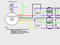
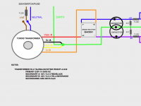
I'm no artist but I think the attached diagram serves its purpose! My main concern was the transformer-bridge rectifier wiring but after reading up I think I've got it...! Each AMP module requires 55v @ at least 225 VA.
If anybody has a spare 5 minutes I'd appreciate your thoughts...
Thanks!
John.
I'm a long time hobbyist but I've only just got into amps and their PSUs (built a couple of 10/15w battery powered so far). I've been doing a fair amount of research into the transformer/rectifier/smoothing setup and have designed a wiring plan for the PSU I need for my amp, based on many hours browsing and a dual supply circuit diagram I found courtesy of ESP here... Power Supply for Power Amplifiers
I'm no artist but I think the attached diagram serves its purpose! My main concern was the transformer-bridge rectifier wiring but after reading up I think I've got it...! Each AMP module requires 55v @ at least 225 VA.
If anybody has a spare 5 minutes I'd appreciate your thoughts...
Thanks!
John.
Attachments

First:
Move the two fuses.
One goes in the mains primary circuit.
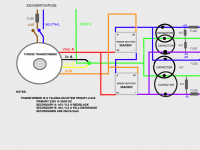
One more goes in the secondary circuit AFTER the main smoothing caps for every polarity. That's five fuses in total.
Use a close rated slow blow in the mains.
Use a fast rated in the supply lines to suit the current output of the amplifiers.
You show a parallel dual polarity supply from a single centre tapped transformer.
There is a thread running now that is discussing the noise at the amplifier outputs when two linked amplifiers are run from paralleled supplies from a single transformer. This set up is extremely difficult to get operating quietly.
4 secondary windings helps attenuate some of this noise as does two dual secondary transformers, but consider also using a single bridge rectifier on each secondary output and then combining these into dual polarity supplies.
Move the two fuses.
One goes in the mains primary circuit.
One more goes in the secondary circuit AFTER the main smoothing caps for every polarity. That's five fuses in total.
Use a close rated slow blow in the mains.
Use a fast rated in the supply lines to suit the current output of the amplifiers.
You show a parallel dual polarity supply from a single centre tapped transformer.
There is a thread running now that is discussing the noise at the amplifier outputs when two linked amplifiers are run from paralleled supplies from a single transformer. This set up is extremely difficult to get operating quietly.
4 secondary windings helps attenuate some of this noise as does two dual secondary transformers, but consider also using a single bridge rectifier on each secondary output and then combining these into dual polarity supplies.
First:
Move the two fuses.
I was wondering about those, the idea was from G Randy Sloane's High Power Amp book to protect the transformer if there was a short circuit in the rectifier
One goes in the mains primary circuit.
Yup got one after the mains switch (just not illustrated)
One more goes in the secondary circuit AFTER the main smoothing caps
for every polarity.
I have 4k7 resistors after the caps to discharge them after the mains is switched off - should I fuse before or after these?
That's five fuses in total.
So one mains, 4 after the the caps - the amp modules are also fused so I actually have 7 in all!! Is that overkill or better to be on the safe side?
Use a close rated slow blow in the mains.
Done!
Use a fast rated in the supply lines to suit the current output of the amplifiers.
Ah, Mr Sloane advises delay fuses to 'be in line with the huge surge currents resulting from the initial charging of the reservoir capacitors'. I guess fast blow offer better protection....?
You show a parallel dual polarity supply from a single centre tapped transformer.
There is a thread running now that is discussing the noise at the amplifier outputs when two linked amplifiers are run from paralleled supplies from a single transformer. This set up is extremely difficult to get operating quietly.
Thanks, I will search out that thread and give it a good read...
4 secondary windings helps attenuate some of this noise as does two dual secondary transformers, but consider also using a single bridge rectifier on each secondary output and then combining these into dual polarity supplies.
OK so Vsec & 0v secondary outputs to rectifier AC inputs for both A & B?
dual rectifier from dual secondaries produces two single polarity supplies.
Join the two single polarity supplies in series and you get one dual polarity supply.
The junction is conventionally taken as Zero Volts and this also becomes the tapping point to run to Safety Earth and another run to the Main Audio Star Ground.
You don't need 4 capacitors, 2 are sufficient. Expect +-58Vdc to +-60Vdc from your 40+40Vac transformer.
Hi Andrew.
I am now somewhat confused...is everything I've learned so far wrong? My transformer has two identical secondary outputs rated at 40v/250VA each, as per the data sheet from Nuvotem (the actual output as measured with my DMM is 46v AC).
I salvaged a chassis from a defunct DVD player and used it to setup a (safe) mock-up of the first stage of the above diagram. Having connected one secondary output to the bridge rectifier (black/red) as expected I obtained a DC voltage at the rectifier outputs (42 volts). Connecting the other secondary (orange/yellow) I again obtained a DC voltage of 42 volts.
Does it not stand, therefore, that as and when I purchase an additional bridge rectifier and connect them as above, I will have two 42v DC outputs, both of which I can then route through my capacitors/resistors to the DC rails of the amp modules?
Kind regards,
John.
After further searching the forum including this thread,
http://www.diyaudio.com/forums/power-supplies/83110-dual-rail-supply-no-centre-tap.html
there appear to be several options regarding this kind of supply…please see below for diagrams...
Option 1:
Each secondary feeds a separate bridge rectifier, creating two DC outputs which in turn feed each amp module via smoothing…
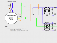
Option 2:
The NEUTRAL of secondary A and the LIVE of secondary B are combined to produce a centre tap (as per the above thread), which is then grounded. The LIVE of secondary A and the NEUTRAL of secondary B are then split to feed two rectifiers which then create 2 DC outputs to feed the amps as above…
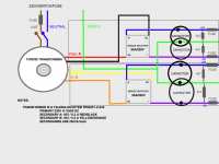
Option 3;
The NEUTRAL of secondary A and the LIVE of secondary B are combined to produce a centre tap. The LIVE A and NEUTRAL B feed one rectifier to create 1 DC output which is then split PRE-smoothing to feed the amp modules…
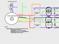
Option 4
The NEUTRAL of secondary A and the LIVE of secondary B are combined to produce a centre tap. The LIVE A and NEUTRAL B feed one rectifier to create 1 DC output, which is split POST-smoothing…
Option 5
As per Andrew’s comments above – Andrew I think this is what you’re getting at (well partially)?
The NEUTRAL of secondary A and the LIVE of secondary B are combined to produce a centre tap. The LIVE of secondary A and the NEUTRAL of secondary B are then split to feed two rectifiers. The outputs from the rectifiers are combined in series to produce 1 DC output, which is then split pre-smoothing…
Personally I see option 1 as the most logical, although this excludes the center tap. I'm continuing my research to ascertain...
1) the importance of the transformer being center tapped...
2) whether grounding one of the secondaries affects the transformer output in any way...
3) whether it's best to split the supply pre or post smoothing or whether this makes no difference...
Any further advice (and/or diagram!) would be appreciated!
http://www.diyaudio.com/forums/power-supplies/83110-dual-rail-supply-no-centre-tap.html
there appear to be several options regarding this kind of supply…please see below for diagrams...
Option 1:
Each secondary feeds a separate bridge rectifier, creating two DC outputs which in turn feed each amp module via smoothing…
Option 2:
The NEUTRAL of secondary A and the LIVE of secondary B are combined to produce a centre tap (as per the above thread), which is then grounded. The LIVE of secondary A and the NEUTRAL of secondary B are then split to feed two rectifiers which then create 2 DC outputs to feed the amps as above…
Option 3;
The NEUTRAL of secondary A and the LIVE of secondary B are combined to produce a centre tap. The LIVE A and NEUTRAL B feed one rectifier to create 1 DC output which is then split PRE-smoothing to feed the amp modules…
Option 4
The NEUTRAL of secondary A and the LIVE of secondary B are combined to produce a centre tap. The LIVE A and NEUTRAL B feed one rectifier to create 1 DC output, which is split POST-smoothing…
Option 5
As per Andrew’s comments above – Andrew I think this is what you’re getting at (well partially)?
The NEUTRAL of secondary A and the LIVE of secondary B are combined to produce a centre tap. The LIVE of secondary A and the NEUTRAL of secondary B are then split to feed two rectifiers. The outputs from the rectifiers are combined in series to produce 1 DC output, which is then split pre-smoothing…
Personally I see option 1 as the most logical, although this excludes the center tap. I'm continuing my research to ascertain...
1) the importance of the transformer being center tapped...
2) whether grounding one of the secondaries affects the transformer output in any way...
3) whether it's best to split the supply pre or post smoothing or whether this makes no difference...
Any further advice (and/or diagram!) would be appreciated!
Attachments
pic5 does not work.
Pics2, 3 & 4 are some of the centre tapped options.
Pic1 is one of a series of dual secondary options.
I have never managed to get a two channel amp using pic3 to be completely silent.
I have had a little more success with pic2, but two channel is not completely silent, in the many ways I have tried to ground it.
I have tried literally hundreds of combinations of ground wires to zero volt reference.
Last edited:
Hello Andrew,
Could you say your experience about this topology: http://www.tnt-audio.com/jpg/psu3.jpg
Interesting, how it compared to pic #4. Is there any difference in the noise floor between them?
Thank you!
Max
Could you say your experience about this topology: http://www.tnt-audio.com/jpg/psu3.jpg
Interesting, how it compared to pic #4. Is there any difference in the noise floor between them?
Thank you!
Max
that's simply dual secondary to dual rectifier.
Pass likes this to avoid warranty returns. He says it helps attenuate mechanical noise from a noisy transformer.
MDM,
do not rely on one Member's opinion.
Learn to sift out what is crap, what is good, which Sources can be guaranteed to be right with their opinion and are able to back it up with fact/data. Do not rely on me for anything. Get corroboration from some/many. Do your homework.
Last edited:
MDM: you took the thought right out of my head!
Johnalexwarren: take a look at this link. Hope it helps
Solid State Power Amplifier Supply Part 1
I have more than passing interest in what your doing... ...I want to do very similar things (PSUs) to several Hafler XL-280s! Short on time & long story for another day.
I agree w/Andrew on gather info to help sift to "right/best/most trouble-free way." I want to get it right the first time like anyone else.
cheers tony
Thanks Andrew, Tony!
I'll try dual secondary to dual rectifier topology, maybe even today. I like to try everything on myself))
I'll try dual secondary to dual rectifier topology, maybe even today. I like to try everything on myself))
Please consider to NOT connect Safety Earth/PE to signal GND. There is no reason to do so as it will only inject pollution from Safety Earth/PE into your audio circuits. I sense a strict difference in reasoning this subject by many including myself but Safety Earth/PE should be directly connected to the metal case (officially, except when things are "double insulated") to avoid being electrocuted when wires get loose etc. It is for safety, please check the guidelines/regulations. Also RF and noise is directed to Safety Earth/PE as is the case with the filters in computer supplies. Just suppose your PE wiring in the house is not ideal and you will get that this RF/noise will be coupled to your audio installations GND.
I am standing on the roof of my house now friendly yelling to everyone that wants to hear : Signal GND has nothing to do with Safety Earth/PE !! I am old skool and have learned the hard way that connecting both will make things worse and it won't be more safe too which makes it useless to do so. It is common with older british gear and it causes more ground loops than one can appreciate. Just think of the antenna cabling of FM tuners which is also connected to PE => loop !
You can connect star GND to the case (which has a connection with PE) with a 100 Ohm resistor paralleled with a 10 nF ceramic cap and the amp will be safe and (RF) shielded. No loops too.
Last edited:
NTC thermistors also could be used between Safety Earth and signal GND to avoid RF pickup, Mr. Pass described it here: http://passdiy.com/pdf/balzenpre.pdf (page 3)
I should have put it this way: Please consider to NOT connect Safety Earth/PE directly to signal GND. Sorry but as a dutchman I make mistakes in english.
As long as it isn't near a few to 0 Ohm by connecting signal GND directly to PE the old fashioned wrong way it won't have the detrimental effects as explained. I have never used the CL60 NTC type and I will try that one one day as it seems a elegant and simple solution. I generally use 1W or 2W 100 Ohm resistors as I had unreliable NTC resistors in the past. 10 Ohm can also be used but I would not go any lower and I would not use standard 0.125W resistors either ! You can be sure that when a 10 ohm resistor is used 230V 16A breakers will trip which is intrinsically more safe than the 100 Ohm that will only trip the Ground Fault Circuit interruptor as used in modern homes here. So 10 Ohm seems a more safe solution but bear in mind that the case should be connected to the PE and this is the official primary safety connection in case of catastrophic connection to the live AC line.
As long as it isn't near a few to 0 Ohm by connecting signal GND directly to PE the old fashioned wrong way it won't have the detrimental effects as explained. I have never used the CL60 NTC type and I will try that one one day as it seems a elegant and simple solution. I generally use 1W or 2W 100 Ohm resistors as I had unreliable NTC resistors in the past. 10 Ohm can also be used but I would not go any lower and I would not use standard 0.125W resistors either ! You can be sure that when a 10 ohm resistor is used 230V 16A breakers will trip which is intrinsically more safe than the 100 Ohm that will only trip the Ground Fault Circuit interruptor as used in modern homes here. So 10 Ohm seems a more safe solution but bear in mind that the case should be connected to the PE and this is the official primary safety connection in case of catastrophic connection to the live AC line.
Earth ground from the AC cord is attached to the chassis for safety, and is connected to the circuit ground through a power thermistor (bright idea from Frank DeLuca). This gives some resistive isolation for prevention of ground loops but goes to small values of resistance in case of catastrophic connection to the live AC line.
Last edited:
Please consider to NOT connect Safety Earth/PE to signal GND. There is no reason to do so....................
You can connect star GND to the case (which has a connection with PE) with a 100 Ohm resistor paralleled with a 10 nF ceramic cap and the amp will be safe and (RF) shielded. No loops too.
This is dangerous.
It is also contradictory.
Read it at your peril.
If you implement what Jean Paul is recommending you are endangering yourself and your family, particularly young children.
I am reporting Jean Paul's post and asking for it's removal.
**, you forgot to mention it could be dangerous for small pets too.
The metal/conductive case is connected to PE as required by law. Signal GND is connected to PE via 10/100 Ohm resistors, a CL60 NTC, 2 antiparallel diodes or in other words so called "lifted". I don't see the point of it being dangerous when the case is connected to PE ?!
PE is meant to protect people from touching gear that makes contact to live AC wiring. Not to directly connect signal GND to. But you would probably want the case to be a shield too for the electronics that are inside hence the connection of signal GND to the case via a resistor. I see it is a can of worms and at the same time I often see gear that have a PE equipped IEC connector not being connected to PE at all in various countries. So it is not an easy subject whilst it is in fact not complicated at all but things are influenced by local habits/regulations that might not be up to date or at the other hand very modern. For example: it is not too long ago that touching the antenna connector of a TV set and touching PE would give an electric shock.
Primary goal of PE connection is that touching metal parts (that could be under live AC voltage because of an equipment failure) presents no danger as it is connected to PE. This should not be underestimated and always be taken in account when building equipment. It might not be you that experiences a failure of your self built equipment but it might be the new owner or indeed your kid.
Last edited:
I have more time now.
to Jean-Paul: what's PE?
to JohnAlex: make sure you read all 3 pages of that PS article. At the bottom of each page is the link to the next. I've read this article many times along w/ others. Please accept my apology for seemingly taking over this thread. DIYaudio has a Hafler thread-I haven't gotten detailed enough answers to try anything. And thank you for your patience.
To any of the more learned & I'm sure that's any other subscriber but me; bottom line: I want completely separate PSUs for my Hafler XL280s sharing only the chassis & power cord. Each channel's PSU taylored/upgraded to perform per my intentions 2 paragraphs below. BTW I can recognize resistors fron capacitors, etc., from 20 paces & I know which is the business end of a soldering iron (earned my living with one) but lack the experience of everyone else.
First some baground on amp in question. http://www.hafler.com/techsupport/pdf/XL-280_amp_man.pdf
Go to pg 16 for parts list; 17 for schematic. You'll see the front end(s) share RB, cap bank, & transformer windings . The finals also share transformer windings, lower voltage however, but enjoy separate left & right RB and cap banks. Also I understand Hafler picked "the right" PS filtering caps. So much so some in other circles claim that a different make &/or model cap "considered an upgrade" by many, isn't.
Why, you wonder, do I want to do this? To take a different approach to maximizing channel separation while bi/tri-amping my HT speakers. I have the EXOs & enough amps to complete the following: connect an XL 280 to my left speaker*; another to my center*; a third to the right*. Further, using the left speaker as an example, connect the left channel to that speaker's tweeter & the right channel to the same's mid. And follow suit with the center and right speaker's XL280s. Crazy? Maybe.
* all of my speakers (Polks) have duel binding posts making bi-wiring**/amping** easy.
** soldering iron makes quick work of the passive filters
I'd like use a higher VA rated transformer & add capacitance to the [amp] channel driving any mids, especially the center speaker*. So I'm in the market for non-working Hafler XL-280s. BTW right now my center is bi-wired w/the left & right channels of one of those XL280s and the rear speakers share one**.
* mids in parallel - 2 ohms!
** Will bi-amp them upon purchase of XL280 #5
Because I ain't "the sharpest knife in the drawer," w/out detailed drawings or instructions I worry anything beyond simple component swaps could be danger to myself or someone else using the amps.
again thanks in advance for your patience and help
tony
- Status
- Not open for further replies.
- Home
- Amplifiers
- Power Supplies
- Dual PSU layout - how does this look?