This is the next phase of my ambitious 7 driver, 2 passive radiator, 4-way, D'Appolito build.
The Mundorf AMT 25CS2.1-R measurements went well. Let's see if I can mesh them to the Accutons. I'll need a lot of help figuring out how to physically time align them. But first some base measurements.
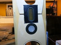
Picture 1) Erik, this is for you. How's that for a makeshift thrown together test baffle? No laughing please!
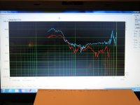
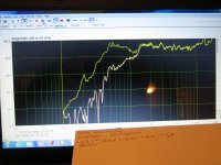
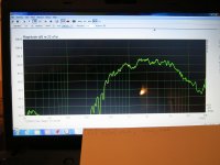
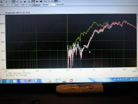
Pic. 2) first frequency response measurement, straight out of the box. Single 68uF safety
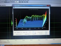
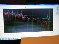
Pic. 3) distortion. At first glance, I'd say usable range is 800Hz to 5KHz. There's a bump in D3 at 7K, and a bump in D2 at 9K.
Pic.4) FR with two 22uF safeties. This will likely be close to the value used for the final crossover. The driver is well behaved, so I started at 400Hz.
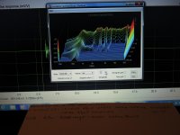
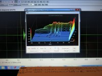
Pic. 5) CSD. From 1K to 5K it's pretty nice. I have something going on with my Focusrite, ignore the bump at 20KHz. The default range of Arta is -25dB. This doesn't tell us enough.
Pic. 6) CSD range now -30dB.
I have a SEAS W26FX woofer in house. I'll use it for a makeshift L-R 2-way Series crossover, cap. 22uF, inductor 1.2mH.
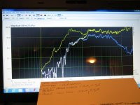
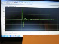
Pic. 7) frequency response. The -3dB point is around 800Hz. For me this is too low. Tomorrow I'll try 1.0mH.
Pic. 8) CSD with woofer. -30dB. The free air resonance around 500Hz is mostly gone. I really like this midrange.
The Mundorf AMT 25CS2.1-R measurements went well. Let's see if I can mesh them to the Accutons. I'll need a lot of help figuring out how to physically time align them. But first some base measurements.
Picture 1) Erik, this is for you. How's that for a makeshift thrown together test baffle? No laughing please!
Pic. 2) first frequency response measurement, straight out of the box. Single 68uF safety
Pic. 3) distortion. At first glance, I'd say usable range is 800Hz to 5KHz. There's a bump in D3 at 7K, and a bump in D2 at 9K.
Pic.4) FR with two 22uF safeties. This will likely be close to the value used for the final crossover. The driver is well behaved, so I started at 400Hz.
Pic. 5) CSD. From 1K to 5K it's pretty nice. I have something going on with my Focusrite, ignore the bump at 20KHz. The default range of Arta is -25dB. This doesn't tell us enough.
Pic. 6) CSD range now -30dB.
I have a SEAS W26FX woofer in house. I'll use it for a makeshift L-R 2-way Series crossover, cap. 22uF, inductor 1.2mH.
Pic. 7) frequency response. The -3dB point is around 800Hz. For me this is too low. Tomorrow I'll try 1.0mH.
Pic. 8) CSD with woofer. -30dB. The free air resonance around 500Hz is mostly gone. I really like this midrange.
Attachments


How do I find my L-R 2nd order 2-way Series crossover values?
1) I go to HiFi Loudspeaker Design . I choose 'calculators'
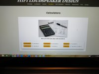
2) at calculators, I choose 'crossovers'
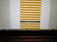
3) at crossovers, I choose 'Series Linkwitz Riley'
4) at L-R, I choose '2nd order 2-way'
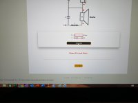
5) I start to play. I am ONLY looking for an inductor value. This is the low pass for the SEAS W26FX woofer, at 8 Ohms. At approximately 1000 Hz it's 8 Ohms. I fiddle with different frequencies until I arrive at the wanted 1.0mH inductor value.
6) 1270Hz looks about right.
7) 1275Hz is also good.
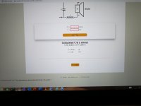
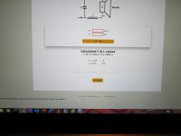
But, but, but, I ignore the capacitor value. The value given is for 8 Ohms. The capacitor is the 'high pass' for the Accuton midrange. The midrange is NOT 8, but 7.1 Ohms. I go back to the 'boxes'.
8) the frequency of 1270 is set, that stays. The new impedance is 7.1. My new capacitor value is 17.65 uF. I ignore the new inductor value of .89mH.
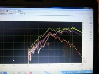
9) the frequency response. Mustard is with a single 68uF safety cap. The yellow is with my L-R series crossover in place.
1) I go to HiFi Loudspeaker Design . I choose 'calculators'
2) at calculators, I choose 'crossovers'
3) at crossovers, I choose 'Series Linkwitz Riley'
4) at L-R, I choose '2nd order 2-way'
5) I start to play. I am ONLY looking for an inductor value. This is the low pass for the SEAS W26FX woofer, at 8 Ohms. At approximately 1000 Hz it's 8 Ohms. I fiddle with different frequencies until I arrive at the wanted 1.0mH inductor value.
6) 1270Hz looks about right.
7) 1275Hz is also good.
But, but, but, I ignore the capacitor value. The value given is for 8 Ohms. The capacitor is the 'high pass' for the Accuton midrange. The midrange is NOT 8, but 7.1 Ohms. I go back to the 'boxes'.
8) the frequency of 1270 is set, that stays. The new impedance is 7.1. My new capacitor value is 17.65 uF. I ignore the new inductor value of .89mH.
9) the frequency response. Mustard is with a single 68uF safety cap. The yellow is with my L-R series crossover in place.
Attachments
-
 IMG_1635.jpg615.3 KB · Views: 140
 -
 IMG_1636.jpg730.6 KB · Views: 111
 -
 IMG_1637.jpg687.7 KB · Views: 93
 -
 IMG_1638.jpg680.3 KB · Views: 100
 -
 IMG_1640.jpg902.3 KB · Views: 111
 -
 IMG_1641.jpg663 KB · Views: 93
 -
 IMG_1642.jpg737.1 KB · Views: 96
 -
 IMG_1643.jpg750.3 KB · Views: 108
 -
 IMG_1644.jpg977.3 KB · Views: 135
Post #3, picture 9, shows the high pass filter. The Accuton now drops closer to our 1270Hz target.
Housekeeping; the woofer is in the room, but 10 feet away, and buried in blankets and pillows. The Mundorf AMT is also in the room, 5 feet away, also buried in blankets. They might contribute a bit, but that's not our concern right now.
Using mh-audio I got my low pass numbers. I have a 0.27mH inductor, so that was my target. I had the Accuton impedance wrong, but I'll worry about that later. For the low pass, I now use 6 Ohms.
The high pass capacitor for the Mundorf is 5.7uF.
Picture shows the frequency response.
Series crossovers have large overlaps, which is one of the many reasons they're avoided. I don't avoid them.
No anomalies from using a Series crossover.
Looks about right. But wait? output is down?. This is a bandpass? The woofer will contribute at the low end (1270 to ? 2000Hz), while the tweeter will contribute below 3600?
Attachments
Time for one of many silly posts.
1) thank you system7 (Steve). About 5 years ago you introduced me to the work of Bud Fried. He believed oversized capacitors sounded better? But, will they give us that fear mongering series crossover picture that made us all afraid of these crossovers?
Pic. 1) Red trace. I added 2 x's 22uF caps, one to each of the 17.65uF caps. This gave us two x 37.65uF
Pic. 2) Green trace. I added 10uF to each of the tweeters 5.7uf caps.
With the exception of moving the -3dB point, no wild output swings. I will concede this is a trace of only one driver. Maybe when the speaker starts to take shape I'll try again.
So far so good.
Attachments


If I didn't have Lee Taylor to cut those tweets in I would have made something a lot worse than you did. Those top and bottom lips being like 2-3 mm wide are murderous to cut in without expert router templating.
OH!! 1 tip I tried which works really well is to use large PSA felt sheets to the sides of the tweets. 🙂
You know... if I was using those parts, I'd put the 2" in a line array to the side of the AMT, and shorten the distance from that to the woofers.
Best,
E
Best,
E
Last edited:
Sorry for the multiple posts. I go away and think about it, then want to return.
The idea is that a D'Appolito design will beam, with less vertical dispersion than normal, but still be perceived as a single point source.
The Mundorf is 130 mm tall, while 2 of your 2" midranges would be around 190 mm tall.
What I would do is try the side by side arrangement, and see if the clarity (lack of room interactions) at the listening position is made better or worse with either arrangement.
Of course, you should also be able to see any differences in the polar plots.
Thank you Erik. I just got home, and am on my way out. I like what your suggesting. I'll let it all sink in, and respond in the morning. Sincerely, Bill.
As I'm ready to push 'Post', I came up with a question: what are the pitfalls of the two 2" being beside the AMT. Please remember, I am only concerned with my 'head in a vice' siting position.
As I'm ready to push 'Post', I came up with a question: what are the pitfalls of the two 2" being beside the AMT. Please remember, I am only concerned with my 'head in a vice' siting position.
Quick felt question; would higher density (10Lbs./sq.yd.) or higher be better or worse?
We're only talking about the tweeter/midrange section. 1000Hz and up.
We're only talking about the tweeter/midrange section. 1000Hz and up.
Billy: For sitting in a vise, none as far as I can tell. Look at the Genesis/Infinity arrays. You will get better beaming of the mids
I mean, in theory, you would have the same lobing issues as a 2-way on its side. Normally, with vertical drivers, the speaker behaves best at or below the tweeter, with above the axis showing significant destructive interference. I imagine that if you use low order filters you might want to use a mirror-imaged arrangement, so the tweeters are on the outside. Of course, using higher order, sharper filters alleviates this somewhat.
Best,
E
Quick felt question; would higher density (10Lbs./sq.yd.) or higher be better or worse?
We're only talking about the tweeter/midrange section. 1000Hz and up.
I don't know. I ended up with a "hack." I didn't originally plan to do this, but I'd had good results with a Focal tweeter, and fortunately for me I asked Lee Taylor to make the fronts black, with rounded corners, so I just bought PSA felt from the craft store, and was happy. 🙂
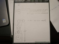
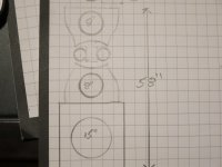
I drew a preliminary sketch. My wife didn't say no!!.
I redrew the tw/mid section as per erik. I'll show it to her, and let you all know what I've decided.
Since the Acoustic Elegance drivers are still a long way away, I have time to think?
I redrew the tw/mid section as per erik. I'll show it to her, and let you all know what I've decided.
Since the Acoustic Elegance drivers are still a long way away, I have time to think?
Attachments

I now have baseline measurements;
The single Accuton C51
Pic. 1) fr in circuit
Pic. 2) distortion of C51 in circuit. Looks good. Dist. is 0.2% or lower in it's intended range.
Pic. 3) Impulse response in circuit. I've never done Imp. measurements. How does it look?. Please comment.
Pic. 4) C51 out of circuit, but with safeties. I'll post a picture latter showing why the lower output (in circuit) was expected.
Pic. 5) AMT in circuit, and with only safeties.
Pic. 6) C51 and AMT
So far so good. Outputs are as expected.
I don't use smoothing. I'm pretty, so my pictures don't need to be?
Tomorrow, using the AMT, I'll try to screw the measurements up. That picture that we've all seen is silly. I'll try to figure out what 'that' person did wrong to get that wild swing in their graph.
Thank you all for putting up with me.
Attachments


Well, that's not what I meant. If you do a horizontal array, you'll end up with narrow mid-beams, and very wide tweeter beams. I meant like this:
8 [ || ]
With the 8 representing the two mids, and the [ || ] representing the AMT.
This will give you more similar horizontal and vertical beaming for the mid and tweet array. ..... but.... experimentation can lead to unexpected results, so don't let me stop you. 🙂
8 [ || ]
With the 8 representing the two mids, and the [ || ] representing the AMT.
This will give you more similar horizontal and vertical beaming for the mid and tweet array. ..... but.... experimentation can lead to unexpected results, so don't let me stop you. 🙂
I'm usually a measurements guy, but we're heading into stuff that your ear/brain will settle better than a mic.
What you want to compare with your choices (D'Appolito, horizontal array straddling tweet, vertical array next to tweet) is clarity at the listening location and off axis performance. I don't mean how it measures, but how it sounds. Can you go off axis and get a good stable stereo image? Which has the best amount of detail and clarity?
What you want to compare with your choices (D'Appolito, horizontal array straddling tweet, vertical array next to tweet) is clarity at the listening location and off axis performance. I don't mean how it measures, but how it sounds. Can you go off axis and get a good stable stereo image? Which has the best amount of detail and clarity?
Here's the kind of alignment i was thinking about, but clearly, not nearly as long. 🙂
An externally hosted image should be here but it was not working when we last tested it.
Picture of projected output's in a 4-way.
Picture of tweeter output; Full range (with safeties), in circuit, with 2 x's 44uf instead of 2 x's 22uf, and finally 2 x's 15.7uF instead of 5.7uf's. No massive swings.
Picture 3; what happens if I accidentally hook the tweeter's -ve lead to where the mids is suppose to go (orange). What happens if I touch the mids and tweeters crossover components together (simulating a tightly packed crossover board, where they accidentally touch)(purple).
Once I start testing the mid and tweet together, I'll again try to replicate the 'series crossovers are bad picture'. I need to know how they got that 'swing'.
Attachments
Last edited:
Series crossovers have large overlaps, which is one of the many reasons they're avoided. I don't avoid them.
Without meaning to cause offense, that doesn't make sense.
 Series crossovers do not 'have large overlaps'. The width of the transition band of any crossover, whether it is series or parallel, active or passive, depends on the electrical and acoustical slopes used. A 1st order acoustical slope is a 1st order acoustical slope. A 2nd order acoustical slope is a 2nd order acoustical slope. A 3rd order acoustical slope is a 3rd order acoustical slope. And so on and so forth. The higher the filter order, the narrower the transition band. QED. It is only the method that differs. A 1st order acoustical slope achieved with a series filter does not magically have a wider transition band than the same 1st order acoustical slope achieved with a parallel filter: they are exactly the same.
Last edited:
- Home
- Loudspeakers
- Multi-Way
- Dual Accuton C51-6-286 2" midrange, D'Appolito, L-R Series x-over