Everything resonates.
With a subwoofer onewants to move (potential) resonances well above the band pass.
To get higher resonate: stiffer, lighter, thicker, less span between braces.
MDF is heavy and not very stiff.
Braces should divide the panels such that no spans are the same (don’t put it in te middle).
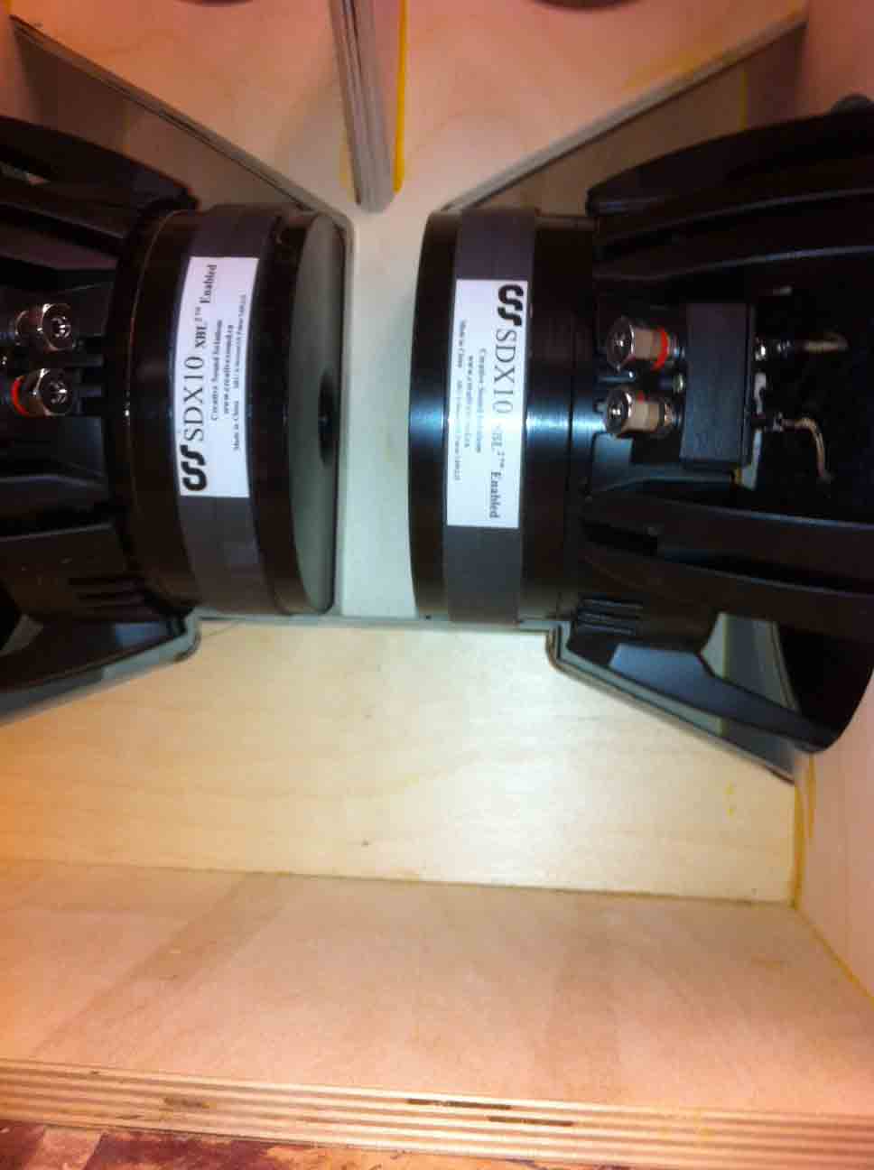
As a test we buikt a push-push 10” using 15mm BB with a simple cross-brace. Wth XO in place, and mains turned off, i had to turn it up well above any sane level and i was only able to get the top to ring. The ampwas likely clipping heavily. A slab of granite on top eliminated that. With no drivers, one could lift the box with a couple fingers in. te driver cut-out, with drivers either 2 peopleora brute.
dave
With a subwoofer onewants to move (potential) resonances well above the band pass.
To get higher resonate: stiffer, lighter, thicker, less span between braces.
MDF is heavy and not very stiff.
Braces should divide the panels such that no spans are the same (don’t put it in te middle).
As a test we buikt a push-push 10” using 15mm BB with a simple cross-brace. Wth XO in place, and mains turned off, i had to turn it up well above any sane level and i was only able to get the top to ring. The ampwas likely clipping heavily. A slab of granite on top eliminated that. With no drivers, one could lift the box with a couple fingers in. te driver cut-out, with drivers either 2 peopleora brute.
dave
Last edited:

Which is close to ZERO in a push-push woofer.
0 x <anything> = 0. The math behind the physics is pretty clear.
And what said earlier about box walk. I would put the mass on top, not into the box. A subwoofer box should have (potential) resonances above the pass band of the loudspeaker. Treat the box resonance issues separatly from having sufficient mass to minimize box walk.
Every material has flexibility. It flexes when pushed by force, it flexes less when it is tougher AND it flexes less if it is pushed by weaker force. Cone and panel mass ratio is important. Think as recoil from the gun: shoot the same bullet from big heavy Uzi or light Glock
So, the panel flexing can be mitigated by better material, more of the same material and by bracing.
Recoil can be minimized by having more mass on the panel in case of push-push.
Thin walls on speakers are due to financial reasons. And there is no need to paint plywood as miracle material - if you can get the same acoustic properties from cheaper material, like MDF then it is a way to go. 24mm MDF beats 12mm plywood in most acoustic properties. The only possible case is the unfavorable resonance freq of the thicker material, but as we have much more mass (and more stiffness) the panel will still resonate less.
Last edited:
Every material has flexibility. It flexes when pushed by force, it flexes less when it is tougher AND it flexes less
In other words everything resonates.
The way you worded things it seems you are talking about air space energy causing ballooning. Any decent construction should have no issues with this. Very stiff at low frequencies.
A majority of the energy that coud excite a resonance comes hru the mechanical reaction of the driver mounted on the baffle.
Recoil can be minimized by having more mass on the panel in case of push-push.
What recoil? Zero = zero.
Why Aluinum/CRS/carbon fibre are so good.
By the time you use enuff MDF to be as stiff as plywood, you need more material and the price differential becomes similar. And don’t forget your BACK.
As well, box material is really not a ignificant part of the investment one makes in a build,
Push-push brings the same advantages no matter what material you use to build it.
dave
Just looked at local supplier: the cheapest 12mm plywood was exactly twice more expensive as cheapest 12mm MDF.
With the same money on materials 2x thickness MDF will beat it in any acoustic property except self-resonance, which is a lottery and can be in other way.
I am telling again: there are no perfect material, there are still some force of driver basket into the panel, even if it is push-push. If there is force - then more strength on that panel is advantage. Bracing just reduces the effect, not fully mitigates it. The only case when it is not, if the drivers are connected between them not through cabinet, maybe with bolts, then the properties of those bolts become relewant.
I’d use the 12mm plywood with the box designed for the material, baffle might need to be doubled to support big woofer — as long as it is quality. 15mm is much easier to work with and supported meaty 10” woofers.
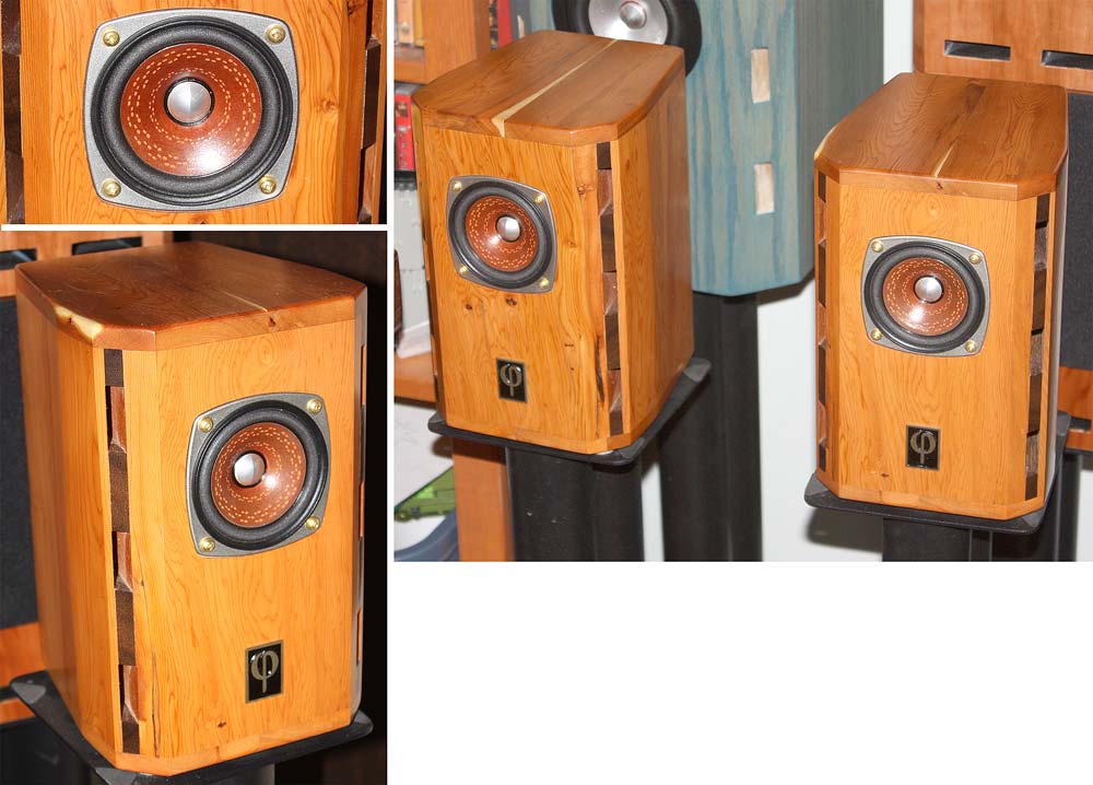
12mm is really only useful for small loudspeakers. Like these (except these are solid yew not plywood.
dave
12mm is really only useful for small loudspeakers. Like these (except these are solid yew not plywood.
dave
I would probably be using 3/4", or 18/19mm. The material will have to be decided based on what is available. BB is getting expensive, but could probably be delivered in a 4'x8' board (1.2x2.4m) for less than $100. This would give me enough material to build two speakers. So the finished product will be a little over 380mm, or 15" in each direction.
A few days ago, I did a nearly minimum sized design just at 13.5". It is probably legitimately too small, and VCAD predicts power handling reductions and big power spikes at low frequencies. But as a test, what would be an adequate bracing strategy for a small container like this? Maybe a simple tic-tac-toe or hastag bracing scheme, but slightly irregular? #

A few days ago, I did a nearly minimum sized design just at 13.5". It is probably legitimately too small, and VCAD predicts power handling reductions and big power spikes at low frequencies. But as a test, what would be an adequate bracing strategy for a small container like this? Maybe a simple tic-tac-toe or hastag bracing scheme, but slightly irregular? #
@D1sco , you can try to connect the drivers together, in the best case rods through driver magnets - but this is unreal.
Or... At least rods from one basket to another:
https://www.diyaudio.com/community/threads/dual-opposing-8-inch.378808/ - this is the way if you have access to the inside of the box
and the same rods just fixed on the outside. You will lose half of the benefits, but still will be pretty much better than classic bracing, but you can do both. Also some threadlocking and anti-loosening tricks will be needed
You can just glue MDF on the inner side of the speaker panels, leave BB just outside: 8-10mm BB + 18mm MDF could make it very good enclosure if you have good hands.
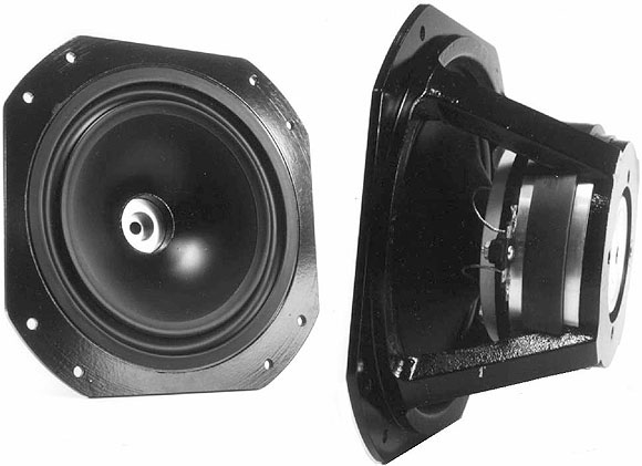
I have these woofers that can be bolted togehter.Note that the magnet is inside the basket. Scott and i worked ona Casle WAW design with a client in Sweden who designed and machined some aluminum fittings for the back of the Scans him to tightly connect the drivers by twisting and locking them together.
This is an illustration of how i first thot i would do it. Shows how ready-rod could be used to hold the bezels together, but having the baffles tighty conected together close to the baffle cut-out. Box width close to the woofer width and additional braces between baffles and top and bottom. With the 10s we used a single brace just off centre that also braced the two drivers together. The minimal box size ( + LW-R transform) here means box all 4 walls act as such.
dave
Last edited:
In this design, I have the bracing a few mm from the magnet and a cutout where I suspect the pole vent will be. My plan would be to put some thick foam surrounding the magnet or cloth to connect and damp it, leaving a gap where the brace has been cut away in the center. Installing the drivers would require compressing this foam, hopefully connecting it to the opposite driver and the brace system. This way any vibration would be reduced by the damping material. Would that be better or worse than direct contact?
Rod through is custom solution. A lot of extra money. If there are some of the drivers, which can be not so painfully modified - it can be interesting. Especially subwoofer drivers. But they are without phase plug and any modification and maintenance is full disassembly of it as bolts have tendency to get loose or the thermal contraction expansion does its thing. Rods with bolts only from outside and some material between baskets seems like a good compromise - easy to make, easy to maintain.
I wouldn’t want the rods to cause bowing or cracking due to differences in temperature/moisture. Even though the box should be airtight. In the spirit of simplification, I am also looking into simple dowels for reinforcement. Tying the panels to each other to distribute energy and dissipate it is the main goal, right? Two simple dowels could do that.
Does anyone have a recommended software for modeling panel flex or resonance?
Does anyone have a recommended software for modeling panel flex or resonance?
As long as you have a competent bracing strategy that connects the opposite walls with each other, and limits unbraced spans of 3/4" material of your choosing to less than 6-8 inches, you will be getting "99%" of the benefits of force cancellation while also sufficiently limiting the panel flex due to box pressurization. As for irregular spacing, it is a best practice where your panels are going to be seeing some higher frequencies that might excite their resonances -- you want to avoid a whole bunch of identically-sized sub-panels that would resonate at the same frequency. The subwoofer signal is already electrically low-passed, so as long as the combination of panel stiffness and bracing has placed panel resonances up out of the sub band, you don't need to worry so much about this either. For the last "1%", then you get into direct mechanical connection between magnets and baskets. IMHO this is diminishing returns territory. Certainly nothing wrong with DIY overkill, but it's questionable if it would be a noticeable improvement in return for the additional build complexity.what would be an adequate bracing strategy
I wouldn’t want the rods to cause bowing or cracking due to differences in temperature/moisture
Never thot of that. It could be a problem, particularily with MDF or solid wood.
dave
As long as you have a competent bracing strategy that connects the opposite walls with each other, and limits unbraced spans of 3/4" material of your choosing to less than 6-8 inches, you will be getting "99%" of the benefits of force cancellation while also sufficiently limiting the panel flex due to box pressurization. As for irregular spacing, it is a best practice where your panels are going to be seeing some higher frequencies that might excite their resonances -- you want to avoid a whole bunch of identically-sized sub-panels that would resonate at the same frequency. The subwoofer signal is already electrically low-passed, so as long as the combination of panel stiffness and bracing has placed panel resonances up out of the sub band, you don't need to worry so much about this either. For the last "1%", then you get into direct mechanical connection between magnets and baskets. IMHO this is diminishing returns territory. Certainly nothing wrong with DIY overkill, but it's questionable if it would be a noticeable improvement in return for the additional build complexity.
Steel threaded rod, lets say M5 diameter will act at far lower force due to contraction for it to be something dangerous for the rod or the cabinet itself. The force needed to break a single rod in tension is measured in hundreds of kilograms or even tons. Also, the temperature difference will be ~30 degrees at the worst in long term and the same in the short term due to heating from voice coil. In any case that is not the temperature difference to worry about.
For 30 degrees the expansion/contraction is ~0,04%, so for 50cm rod that is 0.2mm, very manageable.
Last edited:
wow your fusion chops are superb !Autodesk Fusion360 has a totally different workflow to a lot of modeling software. It all starts with 2D sketches and extrusions/shaping of those sketches. Complex lines are just as valid as my protractor perfect angles.
is there any tutorials that help to draw subwoofer and speaker cabinets ? i tried fusion one time but the tutorial was made to make complex moving pieces and parts of machinery, nothing that i found that can help you draw cabinets and internal panels and bracing for tapped horns and bandpass cabinets
Just to clarify, these are Sketchup drawings, a much lower fidelity software for basic renderings. I wouldn't send a circle cut to a CNC machine from anything less than a Fusion file. IIRC, it doesn't store a curve so much as remember the parameters and draw it as best as possible for each platform. Sketchup draws the most polygonal circle you've ever seen on close inspection, and I've seen the prints.
My favorite, not currently compatible with the MacOS version last I checked due to hotkey changes.tutorials
open the inspector on sketchup circle you want to fix
and where segments are , type 40 or 50 and presto!! problem fixed, smooth circles
idk why sketchup made that on round objects,

Sukkk right ?
default is 24 segments
click on the circle outline
change to 50 or 100

FIXED!!

and where segments are , type 40 or 50 and presto!! problem fixed, smooth circles
idk why sketchup made that on round objects,
Sukkk right ?
default is 24 segments
click on the circle outline
change to 50 or 100
FIXED!!
I took a minute to look into my potential panel resonances and final box volumes this morning. Using the 380mm model and some online references, I have a better estimate of the space these Dayton 12's take up. The magnets alone are a full liter+. The cone displacement is approximately 0.7 L. I am going to guess 3.5L for the pair, which leaves me 33L without bracing.

Next I ran a final rough box sim, with no assumptions of accuracy, to see if the final volume would impede on power handling and extension. It doesn't really. In fact, the smaller box volume does a better job reducing excursion at the lowest frequencies without a latency inducing high-pass filter. This is at the cost of efficiency at the lowest frequencies, but who cares about hearing 10Hz anyways?

Most importantly:
With the panel resonances as high as 500Hz, I am looking at a second harmonic in 250Hz/1khz, a third at ~160Hz and 1.5KHz. Do I even need bracing if the panels are stiff enough, and the resonances are that high? Or I could focus on a single window brace that couples the drivers at the magnet somehow. Very simple.
Next I ran a final rough box sim, with no assumptions of accuracy, to see if the final volume would impede on power handling and extension. It doesn't really. In fact, the smaller box volume does a better job reducing excursion at the lowest frequencies without a latency inducing high-pass filter. This is at the cost of efficiency at the lowest frequencies, but who cares about hearing 10Hz anyways?
Most importantly:
With the panel resonances as high as 500Hz, I am looking at a second harmonic in 250Hz/1khz, a third at ~160Hz and 1.5KHz. Do I even need bracing if the panels are stiff enough, and the resonances are that high? Or I could focus on a single window brace that couples the drivers at the magnet somehow. Very simple.
Nice investigation, I think it's time I learn to use Vcad! I still think bracing is worthwhile, if only to limit cabinet vibration due to panel flex. Not surprised to see that the resonances are well above the sub passband.
I would target a sealed enclosure volume that lets you hit xmax of your drivers given the available amplifier power or driver thermal power limit, whichever is lower. It looks like you've got it pretty dialed in at this point, just make sure the amplifier you ultimately choose can actually deliver the voltage swing with which you're simulating, 57 Vrms in this case.
I would target a sealed enclosure volume that lets you hit xmax of your drivers given the available amplifier power or driver thermal power limit, whichever is lower. It looks like you've got it pretty dialed in at this point, just make sure the amplifier you ultimately choose can actually deliver the voltage swing with which you're simulating, 57 Vrms in this case.
- Home
- Loudspeakers
- Subwoofers
- Dual 10" Mini Sub