Has anyone desoldered the torroid/fuse on the 5V input? Mine is blown and the solder pads are 99% hidden below the torroid.
I am guessing my solder iron will not be sufficient. I have to buy a heat gun or infrared, or the like?
I am guessing my solder iron will not be sufficient. I have to buy a heat gun or infrared, or the like?
Last edited:
Has anyone desoldered the torroid/fuse on the 5V input? Mine is blown and the solder pads are 99% hidden below the torroid.
I am guessing my solder iron will not be sufficient. I have to buy a heat gun or infrared, or the like?
A heat gun would be the best. But it also works with a solder iron. I have had the problem. I carefully destroyed most of the toroid with a small sharp side cutter and after that removed the rest from the solder pads with the solder iron.
Thank you Siginitz. I had taken half the torroid apart already, but was nervous to go much further. Having done as you suggested, it came away in the end.
May need a heat gun in the future, not least for putting the replacement part back on. This looks feasible for the odd time I'll need it 858D 2in1 HOT AIR REWORK SMD SOLDERING IRON STATION LED Display w/3 Nozzles 220V | eBay
Now I need the part. Anyone got the product name, or order code for ordering from UK? Thanks.
FIR filters.
Ok, I've used my Najda for a while now as a 4 way crossover (IIR fitlers). I want try FIR filters. How do I go about converting my traditional crossover to the equivqalent FIR type?
Any advice on how to do this step by step?
I use 6 db/octave crossovers with some EQ here and there.
thanks,
Herman
Ok, I've used my Najda for a while now as a 4 way crossover (IIR fitlers). I want try FIR filters. How do I go about converting my traditional crossover to the equivqalent FIR type?
Any advice on how to do this step by step?
I use 6 db/octave crossovers with some EQ here and there.
thanks,
Herman
Anyone considered this for single ended to balanced conversion of Najda output?
Are there other good alternatives?
ghentaudio --- RTX (unbalnced RCA to balanced XLR) Module
Are there other good alternatives?
ghentaudio --- RTX (unbalnced RCA to balanced XLR) Module
How about a simple RCA-to-XLR cable? A proper differential, balanced input stage doesn't really care if the source is differential or not (as long as you pay attention to avoiding ground loops).Anyone considered this for single ended to balanced conversion of Najda output?
Hello jojip,
I'm also looking at an balanced solution. One possible solution, i was thinking, is the use of transformers. Another possible solution are the following modules for me: Symmetrierverst?rker-Module
I'm also looking at an balanced solution. One possible solution, i was thinking, is the use of transformers. Another possible solution are the following modules for me: Symmetrierverst?rker-Module
Balanced to unbalanced is challenging, unbalanced to balanced is trivial - no fancy electronics or transformers needed. You only need them to turn an unbalanced input into balanced, but not if you already have a balanced, differential input.
Yes a pseudo-balanced cable can easily be used to connect unbalanced source to balanced amp input, but a true balanced interconnect likely allows more robust signaling.
Having said that, a circuit added to the signal path to do unbalanced to balanced conversion has to be of good quality so it doesn't do more harm than good.
Having said that, a circuit added to the signal path to do unbalanced to balanced conversion has to be of good quality so it doesn't do more harm than good.
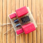
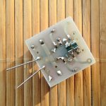
I'm also about to upgrade to balanced outputs. Decided to use THAT 1646 balanced driver chips. Seems to be an attractive solution.
There's only a few components needed around the chip. Went with Wima MKS 10uF caps instead of electrolytics to keep distortion as low as possible.
Designed a small 25x25mm pcb to hold it all together. Each XLR-socket will have a pcb attached right behind it, vertically. Then 4 solid copper wires will run trough all the pcb's, connecting +12V, -12V, GND and pin1 of XLR-socket.
Don't have the back panel ready yet, so only an impression of one of the populated pcb's ...
Attachments
Last edited:
Yes a pseudo-balanced cable can easily be used to connect unbalanced source to balanced amp input, but a true balanced interconnect likely allows more robust signaling.
Why and how?
Real balanced outputs gives less Problems by connecting the components together.
Why and how?
Hi! I was folowing the SE to balanced output discussion. I am not sure if it is for digital or audio signal.
Anyway a very simple solution for audio is the DRV134. This is a high quality chip. I used it many times and always satisfied.
This IC and other op amp arrangements are not usable for digital applications.
Anyway a very simple solution for audio is the DRV134. This is a high quality chip. I used it many times and always satisfied.
This IC and other op amp arrangements are not usable for digital applications.
What about balanced to unbalanced solution? I have balanced out from preamp with a long run that I want to go to Najda.
Recommendations?
Herman
Recommendations?
Herman
Why and how?
A true balanced output provides similar output impedance on both leads, any induced noise voltage is similar and allows best common mode rejection at the differential input at the receiver.
A psuedo-balanced interconnect offers most of the goodness but the common mode rejection may not be as good.
A true balanced output provides similar output impedance on both leads, any induced noise voltage is similar and allows best common mode rejection at the differential input at the receiver.
How do you define "output impedance" in a balanced scenario? The impedance the differential input stage cares about is the one between the inverting and non-inverting input - it doesn't care what the impedance between either of those two and the source ground/earth/whatever is.
Right - but considering you have no common mode rejection at all with an unbalanced connection, a "pseudo-balanced" connection (a bit of a misnomer, as the connector itself is balanced) is really almost as good as a fully balanced one, so any extra electronics or transformers are hard to justify.A psuedo-balanced interconnect offers most of the goodness but the common mode rejection may not be as good.
Balanced is also about balancing impedances, not just to do with looking at differential signals
There are loads of references, so have a search
This can be used as a starter:
Balanced Interfaces
Have a look at the section The Balanced Interface
There are loads of references, so have a search
This can be used as a starter:
Balanced Interfaces
Have a look at the section The Balanced Interface
- Home
- Source & Line
- Digital Line Level
- DSP Xover project (part 2)