How does the signal look before and after the resistor?
Does the IC drive the FETs directly or through an emitter follower pair?
Does the IC drive the FETs directly or through an emitter follower pair?
The ic drives the fets directly .
I replaced the resistor just to be safe .
I’m going to replace the ic again since I had issues with the ic’s on the other amp.
Just gotta wait for the parts to arrive later today and will update the post later
I replaced the resistor just to be safe .
I’m going to replace the ic again since I had issues with the ic’s on the other amp.
Just gotta wait for the parts to arrive later today and will update the post later
Replaced the driver ic’s diode is still lifted .
The fets still get hot and amp draws excessive current .
Q15,16 are the fets that heat up the most .
Any ideas ?
The fets still get hot and amp draws excessive current .
Q15,16 are the fets that heat up the most .
Any ideas ?
Replaced the driver ic’s .
All fets are removed from the amp and loaded with a 0.1 uf cap .
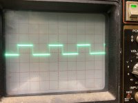
Scope settings are 5us 5 volts/div
Pic 1 is the drive wave coming into the 4427 pin 2
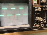
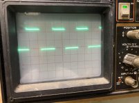
Pics 2,3 are the drive wave coming out of the 4427 pins 5,7
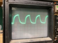
Pics 4,5 are at the gate legs of the fets
I think these look ok unless I’m over looking something.
All outputs are removed from the amp so if the drive wave looks ok something else is defective causing the amp to draw excessive current
All fets are removed from the amp and loaded with a 0.1 uf cap .
Scope settings are 5us 5 volts/div
Pic 1 is the drive wave coming into the 4427 pin 2
Pics 2,3 are the drive wave coming out of the 4427 pins 5,7
Pics 4,5 are at the gate legs of the fets
I think these look ok unless I’m over looking something.
All outputs are removed from the amp so if the drive wave looks ok something else is defective causing the amp to draw excessive current
Attachments
-
 6487A88F-E04A-4E10-B63F-C7C4057049E8.jpg961.5 KB · Views: 63
 -
 C6E1C2E4-3B03-4B8C-9FD7-B9CDA7C25385.jpg987.8 KB · Views: 113
 -
 5B7154FA-8D15-415E-A21F-FFF44C70D33D.jpg980.6 KB · Views: 59
 -
 45316B2B-9E09-4CA3-998B-3BBDF9BCB00A.jpg991.4 KB · Views: 61
 -
 6CC26522-C99F-4165-B2E9-9E57B24B1912.jpg983.8 KB · Views: 54
The rectifiers are out of the amp .
Fet locations Q15,16 (IRFP7530) still get very hot and the amp draws excessive current.
So I’m guessing the problem is in the power supply somewhere since the rectifiers are removed and the amp is still doing the same thing.
Fet locations Q15,16 (IRFP7530) still get very hot and the amp draws excessive current.
So I’m guessing the problem is in the power supply somewhere since the rectifiers are removed and the amp is still doing the same thing.
I have no diagram. Are those 2 transistors the only ones in a parallel group?
Do those 2 locations heat up, no matter which transistors are installed there?
Are the drive signals for those two locations identical compared to all other locations when FETs are installed (or loaded with a cap)?
Do those 2 locations heat up, no matter which transistors are installed there?
Are the drive signals for those two locations identical compared to all other locations when FETs are installed (or loaded with a cap)?
Yea those 2 heat up no matter what transistors are installed there .
And the drive signal looks identical to all the others .
I’m wondering if I got a bad batch of fets .
Everything checks fine drive signals are ok but as soon as you put a fet in the location the amp draws excessive current
And the drive signal looks identical to all the others .
I’m wondering if I got a bad batch of fets .
Everything checks fine drive signals are ok but as soon as you put a fet in the location the amp draws excessive current
Yes all 8 fets are in parallel inline with Q15,16
I pulled all the fets rechecked the drive signal and put 1 fet in per bank in different locations .
It doesn’t matter where you install the fets the amp will draw excessive current .
If I install the diode back into the driverboard the amp will not power up it’s stuck in protection mode .
If I lift the diode that’s when I get the problems
I will cut the zip ties and try to remove as much of the silicone as I can so I can twist the transformers to see if that works
So far I twisted the transformer I suspected of being the issue.
I put 2 fets per bank and the amp powers up now and idles fine .
I will put the rest of the fets in the amp and see if it will power up if so I will have to pull/twist the transformer to see if I can find the short
I put 2 fets per bank and the amp powers up now and idles fine .
I will put the rest of the fets in the amp and see if it will power up if so I will have to pull/twist the transformer to see if I can find the short
Found the short it’s on the top side of the transformer it was under the glue .
I’m gonna insulate it and finish putting the rest of the parts back in and see if there are anymore issues
I’m gonna insulate it and finish putting the rest of the parts back in and see if there are anymore issues
Now i have an issue with the rectifiers.
Is there a good way to check them out of circuit ?
Set meter to diode check ?
Is there a good way to check them out of circuit ?
Set meter to diode check ?
If the package is marked with the internal diode configuration, you check them like any diode, using the markings as a guide.
One of the rectifiers is shorted .
The original is FMG36R
Will the FMU36R work as a replacement?
The original is FMG36R
Will the FMU36R work as a replacement?
The FMU is slower which may make it run a bit hotter. I don't know how close to the edge this amp is, as far as design goes. So, my answer is... probably. If the owner is running the amp below the lowest rated load, it's less likely to survive than the original.
- Home
- General Interest
- Car Audio
- DS18 Amp