Hello, i'm trying to design a synchronous buck converter with SG3525 and IR2110, but i ran into a problem: The sg3525 cant drive the IR2110 (and so, the half bridge) with more than 50% duty cycle, resulting in the output voltage not going higher than 50% of the input voltage.
What i wanted to ask is:
Is there a way (Maybe with logic Gates or OpAmps?) to mix the SG3525's outputs in such a way that i obtain waveforms (that i can feed to the IR2110) that go all the way to ~100% duty cycle?
There are other mosfet drivers like IR2184. It requires only 1 PWM input to drive the half bridge. It seems like it 'duplicates' the input signal. But the two outputs of IR2184 are complementary, so they can drive a half bridge with close to 100% Duty cycle.
But SG3525's output are not truly complementary.
I'm really glad if you could help me find a method to make this work.
This is a personal project, i wanted to design and build very efficent and powerful DC-DC converters. But there are still things that i dont know well.
Last thing: I am using drivers like ir2110 because they have larger gate driving currents. I've found others that go up to 4.5A.
Thats because i want my design to be as efficent as possible (Lower switching losses). I'm using mosfets with just 1.8mOhm RDS ON! There two pairs of two mosfets in parallel. So each pair is just 0.9mOhm or 900uOhm! They stay pretty cold even at 20A, which is really impressive.
But now i need some help with this duty cycle dilemma...
I'm using a switching frequency of 100Khz and some deadtime. My circuit works fine even at 30A output current, but i needed the voltage to go very close to the input voltage at maximum. (Thats because i wanted to make it adjustable).
Last edited:
As yourself said: 50% is the maximun duty cycle. So the obvious solution is to choice another IC: the TL494, UC384x will be your next choice. Or perhaps a discrete solution: a ICL7556 as oscillator and monostable as PWM, an opamp controlling duty cycle and eventually some discrete logic to control shortcircuit, overload, too low or too high input voltage or any other issue. I used this solution in my 100KHz solar cell regulator.
I know, you're perfectly right. But for now i just needed this temporary solution, also because i dont have other ICs... And i already soldered everything into a prototype board...
Next time i'm going to learn how those other ICs work and use them for future projects.
For now, what about joining togheter the two outputs of SG3525 with two diodes? (Sb2200).
Then feed this unified signal into the high side input of IR2110 (HI).
Then invert this signal with an inverting OpAmp (LM358) and feed it to the low side input of IR2110 (LI).
And that SHOULD give me two perfectly complementary outputs, suitable for driving a half bridge properly with a duty cycle that reaches close to 100%.
Would this work?
And if it works, will the deadtime remain intact?
The problem is that i dont have an oscilloscope... And i have much less experience in manipulating signals.
If this actually works, let me know.
Thanks!
Last edited:
For now, what about joining togheter the two outputs of SG3525 with two diodes? (Sb2200).
The max 50% odd-even pulses from ICs like 3525 are meant to drive isolated SMPSs. However, you may combine the pulses using an OR-gate to obtain double the duty. Since the max duty is only 50% and the pulses never overlap, an XOR-gate would also work.
Using diodes to combine them is equivalent to an OR gate, so yes, it'd work.
An op-amp is not fast enough, you'd have to obtain the complement using digital logic. I'd suggest using a quad XOR gate like CD4070 (not 74HC86) to obtain dead-time and complementary outputs simultaneously, as shown below.Then invert this signal with an inverting OpAmp (LM358) and feed it to the low side input of IR2110 (LI).
https://www.diyaudio.com/community/...th-level-shift-capability.206636/post-2908874
I'm using mosfets with just 1.8mOhm RDS ON! There two pairs of two mosfets in parallel. So each pair is just 0.9mOhm or 900uOhm! They stay pretty cold even at 20A, which is really impressive.
..... i dont have an oscilloscope...
Well, in that case, you'd have to check the average (filtered) value of the pulse train on a multimeter while varying the PWM reference to see if it varies in proportion.
What MOSFETs are these and what is their gate charge specification ? The Rds values you mention do not usually belong to light gated MOSFETs !! If the switching freq ends up being too high, the 2110 may not be able to drive these correctly ..
Once you get the duty pulses and the complement right, you could add the 2110 and the MOSFETs with the best PCB layout possible and hope for the best. It may be difficult to add snubber etc. without an oscilloscope.
Last edited:
Alright, i'll try my best and see what i can do. But i didnt get very well what to do to get the complementary outputs.
I just need to use the XOR gates for the inverted signal, right? Because the first non-inverted signal... I can get it by using 2 diodes. Right?
The dead time is already generated by the SG3525, but i didnt understand if i have to use the XOR gates to generate the deadtime (Thats in this case it should not be necessary because the sg3525 already generates it, right?). Or this dead time 'gets lost' in this 'signal unification' and i have to re-implement it using those XOR gates?
Another thing that i forgot before:
To let the sg3525 output its maximum duty cycle (So ~50% on output A and ~50% on output B), i should connect the non inverting input of the internal comparator to Vref (5V, pin16) and the inverting input to ground, right? (I need this for testing).
About the MOSFETS, they are HSP0076A (100V, 1.8mOhm, 200nC@10V, Ciss = 13370pF). IR2110 can source / sink with 2A of current. It works well at... Actually 50 kHz (because the frequency is halfed on the half bridge) because, as i said before, the MOSFETs barely heat up even at 20A load. So i'm ok for the POWER part. This is also on a prototype Board. Once i see that everything is working properly i'll proced to make a very good PCB layout on some PCB making software. Then order the PCBs online. I will also use a better mosfet driver capable of 4.5A source / sink.
Yes, the only obstacle that i'm encountering right now is this. The duty cycle.
If you can (and if you have time) (no pressure at all) you can send me a schematic so that i can understand better what to do. Including SG3525 (just the output part), IR2110 and additional logic ICs.
So that this synchronous buck converter will finally be able to output close to Vin (MAX) instead of just 50% Vin.
Thank you for the help 😉
Last edited:
Combine using 2 diodes + resistor. Use the circuit in the above link to get LO and HI with deadtime.I just need to use the XOR gates for the inverted signal, right? Because the first non-inverted signal... I can get it by using 2 diodes. Right?
Yes, 3525 dead time is lost, XOR gets them back ...The dead time is already generated by the SG3525, ... Or this dead time 'gets lost' in this 'signal unification' and i have to re-implement it using those XOR gates?
Not sure, but you can try either way and see what duty results at the outputs using a meter ..To let the sg3525 output its maximum duty cycle (So ~50% on output A and ~50% on output B), i should connect the non inverting input of the internal comparator to Vref (5V, pin16) and the inverting input to ground, right? (I need this for testing).
If the power part works ok, there's nothing much to fear about the duty pulses.About the MOSFETS, they are HSP0076A (100V, 1.8mOhm, 200nC@10V, Ciss = 13370pF). IR2110 can source / sink with 2A of current. It works well at... ...So i'm ok for the POWER part. ... the only obstacle that i'm encountering right now is ... duty cycle.
You could find a lot of circuits that use 3525 and 2110 here on this forum, especially from sometime ago. The logic circuit I cited above is also from within the forum.If you can ...send me a schematic so that i can understand better what to do. Including SG3525 (just the output part), IR2110 and additional logic ICs.
Alright, but how do i calculate the period in ns / us of the deadtime implemented with the XOR Gates? So that i can select the proper resistors and capacitors. I need it to be 500nS. After i know this last thing i will be finally able to make it work.
Last doubt: Are those XOR gates really that much relayable? Even more than fast OpAmps? Can they handle 200 - 500Khz signals?
Will my design be relayable using theese XOR gates to handle the signals for the mosfet driver?
There will be no errors / distorsion in the signal, right?
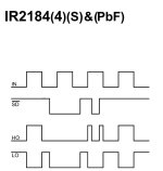
So in the end will finally get the output complementary waveforms that will look like this (see image) (ignore SD) and with a duty cycle that can go up to ~100%, right?
Is the problem finally solved!?
I'm going to make a schematic and i will upload it here after a bit.
Last doubt: Are those XOR gates really that much relayable? Even more than fast OpAmps? Can they handle 200 - 500Khz signals?
Will my design be relayable using theese XOR gates to handle the signals for the mosfet driver?
There will be no errors / distorsion in the signal, right?
So in the end will finally get the output complementary waveforms that will look like this (see image) (ignore SD) and with a duty cycle that can go up to ~100%, right?
Is the problem finally solved!?
I'm going to make a schematic and i will upload it here after a bit.
Attachments
Woah! Nice to know!
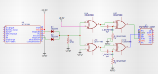
Look at this schematic:
Is that it? Is this right?
I only need the values for the resistors and capacitors to get a dead time of 500ns.
Hopefully there will be no shootthrough in the half bridge with the implementation of the XOR Gates.
Let me know if this is right. So that i will proceed making it in the prototype board and then see if it works.
Once again, thank you so much for all the help.

I know, some gate drivers have integrated dead time like the IR2184. But IR 2110 does not have integrated deadtime.
Most gate drivers with separated input (HI & LI) dont have integrated deadtime.
So i need this circuit (If it works) to generate deadtime so that (hopefully) i wont get any shootthrough on the half bridge.
If it works the synchronous buck converter will finally be able to output a maximum voltage which is close to Vin.
In the end, this will become a 80V 50A rated synchronous buck converter with adjustable voltage and current.
I'm actually using a shielded hall-effect sensor to accurately sense such a big current.
If i can make it, this will basically become my lab bench power supply.
Powerful, durable, efficent... And easily repairable!
In the future i will implement an even more powerful buck converter for a MPPT solar charge controller. Rated at like... Few tens of kilowatts.
Good understanding of the half bridge will also allow me to design powerful class D audio amplifiers. Power electronics are really cool...
Last edited:
Ok, alright. But the solution with the XOR gates will also work, right?
I even have the CD4070! I had a variety of logic ports ICs laying around, and luckily i just found the IC i needed!
So, lets see if this solution works first. Its probably more relayable too, i guess.
I just need to know how to calculate R and C for a 500nS deadtime.
I even have the CD4070! I had a variety of logic ports ICs laying around, and luckily i just found the IC i needed!
So, lets see if this solution works first. Its probably more relayable too, i guess.
I just need to know how to calculate R and C for a 500nS deadtime.
Interesting...
For now, i will try to do it with the CD4070.
I could have gone trial and error with R and C... IF i had an oscilloscope!
Does somebody know how to calculate R and C?
Once i know, i will finally be able to solve this problem.
I will even be able to design isolated half bridge boost converters, to generate a dual rail supply from a single supply (Like a battery) to power high power dual rail amplifiers.
SO, the laaaast thing i need to know is just how to calculate R and C for a deadtime of 500nS.
The last obstacle in the road!
Last edited:
Nice, but you seem to drive the complement into HI and the straight pulse into LO, which might give an inversion at the output. This is why one needs to test the duty pulses for polarity and proportionality.Schematic:
There's no calculation which is why you'd have to simulate. Besides, the dead-time could also vary on the threshold levels and make of the CD4070. I would start with a large capacitor (say 1nF) as recommended by Osvaldo de Banfield and iterate according to the shootthrough and heat that results.Does somebody know how to calculate R and C?
Well, if i had a oscilloscope it would have been waaaay easier...
Anyway, i'll try this out and see what i get.
I am going to flip the connections on the ir 2110.
I am using polyestere capacitors, hopefully they're fine for this Application.
At 100kHz the period is 10uS.
So i'm guessing that 1uS deadtime will 'suck up' 1/10 of the energy thus 'limiting' the total duty cycle at 90% (I may be wrong here).
I may have to select an even lower deadtime like 250 / 100 nS for higher frequency applications. Hopefully i will be able to obtain short and precise deadtimes with that XOR gate solution.
Thank you all for helping me out!
I also learned new stuff too.
In few days i will modify the circuit and update the results. Lets hope for the best!
- Home
- Amplifiers
- Power Supplies
- Driving IR2110 with SG3525 for a synchronous buck converter