After reading the speculation and calculations of some of these effects, I'm having a go at measuring some of them. The first thing I wanted to look at was distortion products in the current waveform (both harmonic and IM) that might be due to Le(x) and Le(i) and I have to say the results are a bit depressing, (in terms of the driver measuring much worse than I expected) and there is also something that is inconsistent with what's expected from the "Overview of symptoms" table on Linkwitz's page that maybe someone can shed light on.If you measure mid band output while shifting static rest position then you have found Bl(x). You then know all there is to know about the AM intermod properties.
To measure the current waveform I sampled the voltage drop across a 0.33 ohm resistor. (Originally I tried 0.1 but I wasn't able to get enough SNR in the measurement so I raised it a bit even though it may skew the results slightly)
The driver is in its bass reflex cabinet tuned to 43Hz but with no crossover components, just the 0.33 ohm resistor in series with an 8 ohm driver. For each current measurement I also took a voltage measurement as a control - in all cases all distortion products were at least -80dB from the fundamentals, at or below the measurement noise floor. (I haven't included them as they don't show anything useful)
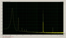
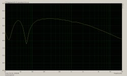
Image 1 is the current spectrum with a two tone test of 60Hz and 2Khz, SPL is about 93dB/1M for the 60Hz tone, and 87dB/1M for the 2Khz tone. Total power about 1 watt, and excursion maybe +/- 0.5mm. (Estimated by eye)
The first thing I notice is what looks like really high 2nd harmonic distortion of the 60Hz signal in the current. (-30dB) Because the impedance is quite high at 60Hz (it peaks at around 70Hz in the bass alignment) and we are measuring the current it does suppress the apparent level of the fundamental, (making it maybe -40dB) but even so it doesn't look good at all considering the modest SPL and excursion for an 8" driver.
Not only that but 3rd, 4th, and 5th are all visible, I wasn't expecting to see a significant level of 4th or 5th. Do we have any mechanism by which 4th and 5th order distortion can be produced in the current waveform ? Flux modulation ?
Up at 6Khz we see the 3rd harmonic of 2Khz, whether or not 60Hz is present. What would the mechanism be for generating 3rd harmonic distortion of 2Khz in the current waveform ? Flux modulation ? Strange there is no 2nd harmonic, or it is below the noise floor.
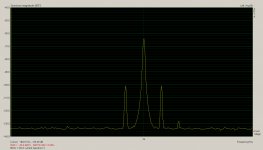
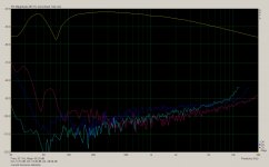
Image 2 I have zoomed into the IM distortion products around 2Khz - there are clear IMD2 products there at about -36dB, and a little bit of IMD3 on the high frequency side. Again for a modest excursion this was a lot more than I was expecting.
According to the table on Linkwitz's page, Le(i) flux modulation will produce both harmonic and IM distortion in the current while Le(x) will only produce IM distortion, so I decided to redo the test with the bass tone shifted to the box tuning frequency at 43Hz.
Compared to the first test we're increasing the current significantly (since we're at the low impedance saddle) but reducing the excursion dramatically.
Correct me if I'm wrong, but in theory distortion produced by flux modulation won't see a reduction from the reduced cone excursion at box tuning, in fact it should see a significant increase from the increased drive current - the cone may be moving less but the force factor from the motor is greater due to the low impedance point.
On the other hand distortion produced by Le(x) should drop, as its proportional to excursion not current.
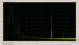
Image 3 and 4 are the same tests repeated with 43Hz, everything else left the same. The first thing I notice is the 2nd harmonic distortion seems to have dropped a lot (remember this is current waveform not acoustic output) but that could partly or largely be because now the fundamental is at a low impedance point and the 2nd harmonic is at a high impedance point, so there may be no net difference. 3rd, 4th, 5th harmonics have all dropped dramatically, but by what mechanism ?
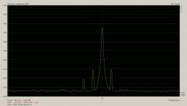
On image 4 the IMD2 products have both dropped considerably to -46dB, despite more voice coil current at bass frequencies, which suggests they've dropped in response to excursion reduction. Curiously now there is an IMD3 product on the low side instead of the high side.
What doesn't make sense to me is that the IMD products, which the chart says can only be Le(x) not Le(i) have dropped as expected with reducing excursion, but so has the harmonic distortion of the bass note, which should have stayed the same or increased due to increased drive current.
If we were measuring acoustic output the result would make sense, but we're measuring drive current, so if flux modulation is the major factor in harmonic distortion of the bass drive current, why is the harmonic distortion of the drive current reducing just because excursion is reducing. I'm a little bit baffled by this one.
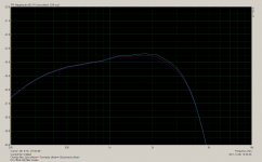
For reference the last image is the current frequency response with a flat voltage input, eg the inverse of the impedance curve. Interesting to see that Le amounts to an almost 10dB loss in potential output by 10Khz. There must be a lot of directivity increase to keep the on axis response roughly flat.
Later on I'll see if I can measure changes in passive low pass filter response with DC offset, I'm not sure if I have the bits I need to do that but I'll see.
Attachments
Last edited:
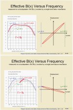
If the entire mid band response drops with DC offset that's Bl(x), but if only the higher frequencies roll off (driver on its own) or the crossover starts peaking, that's due to increasing Le, surely ? The two can be distinguished, although on many drivers they will be happening at the same time which will confuse the issue.If you measure mid band output while shifting static rest position then you have found Bl(x). You then know all there is to know about the AM intermod properties.
David S.
Regarding the Le(x) and passive crossover Q question, a number of years ago I looked into something like this. The initial purpose of the investigation was to look at the effects of VC heating but it ended up looking like what was observed was Le(x) bebavior. You can view the old web page HERE. When the way back pahe come up click "Impatient " at the bottm, center right of the page.
Interesting page John.
One thing of note from it is that the difference in response shape you're seeing from Le(x) around the crossover frequency (if that's what it is) is due to the fact that your MLSS signal is stimulating the driver at all frequencies at once, thus producing excursion and high frequencies at once.
If you had done a log swept sine measurement the change in response shouldn't show up, because excursion and high frequencies won't be present at once.
That's an interesting idea actually that I could test, ARTA can generate an impulse response from a log swept sine, MLSS, or pink spectrum random phase multi-sine signal, on the log swept sine I'd expect to see no effects of Le(x) in the response at the crossover frequency, and in the other two I would, especially with the pink spectrum which will generate a lot of sub sonic excursion.
I'll add it to my to-try list... 🙂
Last edited:
I forgot to include a harmonic distortion vs frequency graph. (measured with log swept sine) Looking at that its clear that the current waveform has significant 2nd harmonic distortion that peaks right at 60Hz, dips around 43Hz, and rises again below. In other words its largely proportional to excursion. Hmm... (Looks like I picked the worst possible frequency at 60Hz...)What doesn't make sense to me is that the IMD products, which the chart says can only be Le(x) not Le(i) have dropped as expected with reducing excursion, but so has the harmonic distortion of the bass note, which should have stayed the same or increased due to increased drive current.
If we were measuring acoustic output the result would make sense, but we're measuring drive current, so if flux modulation is the major factor in harmonic distortion of the bass drive current, why is the harmonic distortion of the drive current reducing just because excursion is reducing. I'm a little bit baffled by this one.
(The graph is not reliable above about 400Hz as the noise floor encroaches, I can't get around that in my current measuring set-up)
Attachments
If the entire mid band response drops with DC offset that's Bl(x), but if only the higher frequencies roll off (driver on its own) or the crossover starts peaking, that's due to increasing Le, surely ? The two can be distinguished, although on many drivers they will be happening at the same time which will confuse the issue.
I mentioned midband because I thought you were concerned with Bl(x), but yes, HF drop with excursion would be the combination of the two effects.
One way to seperate them out would be to measure impedance with the cone physically displaced (doesn't Klippel use air pressure? You can just as easily force the cone by hand).
An interesting demo would be pink noise on to of a 0.5 Hz sine wave. With a "bad" woofer you would hear the total effect (level and bandwidth) of response varying with displacement.
The time I heard the effect was very heavy pink noise drive. The woofer in the particular box allignment had the cone jumping a lot and as it came forward the inductance fell and bandwidth extended. Otherwise in practice it is not a phenomonon that I loose sleep over.
I do think that mid band output as the driver is forced over its excursion range is a good way to divine Bl(x) from a driver. Simply seeing excursion vs. current won't let you seperate Bl falloff from stiffness rise.
Glad you are doing the tests and will study them in depth later.
David S.
Further to this, below is a difference curve between a FR sweep on my Delta 15 with and without -4VDC on the VC, crossover in place. (Response dropped with VC displaced inward)
There is obviously something going on beyond a flat loss. How much effect it is having is not clear but there is a very subtle conditional level dependent distortion that I have been trying to track down and this might have something to do with it. FWIW my crossover may not be typical.
Regarding the Le(x) and passive crossover Q question, a number of years ago I looked into something like this. The initial purpose of the investigation was to look at the effects of VC heating but it ended up looking like what was observed was Le(x) bebavior. You can view the old web page HERE. When the way back pahe come up click "Impatient " at the bottm, center right of the page.
Ok, here is my result. This is with the same driver being driven by it's passive 3rd order 4Khz low pass filter with zobel.
To do the test I put a parallel collection of bipolar electrolytics (amounting to about 120uF) in front of the crossover and measured the voltage response at the driver. (Measuring the current response might have been interesting too, but I've run out of time for now) I used a 150 ohm resistor from the output of the caps and switched it between ground, +12v and -12v. DC offset each way was nearly Xmax.
The extra cap rolls off the low frequency response below a few hundred Hz, but I don't think it will influence the results of the test too much.
Red is zero DC offset, dark Blue was positive (forwards) and light blue negative. (backwards) The only significant change is between 1Khz and 3.5Khz - a bit lower in frequency than I expected when the crossover frequency is 4Khz.
Presumably inductance is increasing in the backwards stroke, raising impedance and causing some voltage peaking of the crossover, (raising its Q) conversely the forwards stroke must be lowering inductance and impedance thus lowering the Q of the network and giving a more saggy response.
Since the voltage is changing due to a change in driver impedance its probably not the right way to look at it when current is what generates the motor force. At the point where voltage is peaking current will probably be staying the same and drooping on either side where the crossover voltage is not peaking. If I get a chance I'll measure current next time.
Total shift is quite small though, amounting to less that 1/4 dB in either direction. Because the in stroke increases it and the out stroke decreases it it should produce primarily even order distortion, but conversely the average RMS level will remain about the same with AC excursion.
Noticeable ? I don't know, probably not at this level of variation with full Xmax. Fall off in BL at Xmax is probably far more dramatic in affecting the acoustic response.
Attachments
Last edited:
Pressing the cone manually if you're trying to measure the voltage across the driver isn't very successful I've found, because you can't hold it perfectly still, so the small movements of your hand introduce very low frequency generator action that messes up the measurement. DC with a specially provisioned amplifier that will allow adjustable DC offset would be the ideal way.One way to seperate them out would be to measure impedance with the cone physically displaced (doesn't Klippel use air pressure? You can just as easily force the cone by hand).
That's an idea I thought of many years ago but never got around to trying out. Apply both a mid frequency tone (say 500Hz) and a variable DC offset at once, vary the DC and measure the fall in measured tone with displacement and plot on a graph. This should be the BL curve independent of the suspension.I do think that mid band output as the driver is forced over its excursion range is a good way to divine Bl(x) from a driver. Simply seeing excursion vs. current won't let you seperate Bl falloff from stiffness rise.
I guess if you went too high in frequency that Le(x) would skew your result but a way to solve that would be to use current drive so Le(x) wouldn't interfere with the result.
The main thing that stopped me was not having an easy way to apply the DC offset, nor measure excursion accurately. But it seems sound in principle.
Last edited:
Next round, and I have run +/-4V at the amp, with and without a crossover. Series resistance in the crossover was compensated for. All plots are difference curves in response magnitude relative to zero offset in each case.
Image 1: Positive - blue, negative - brown. Crossover in place.
Image 2: Without crossover.
Image 3: Both positives.
Image 4: Both negatives.
Firstly, it would appear from this that the crossover is not having a great effect and it is the driver that is independently behaving badly.
Secondly, there appear to be two different effects. One visible below 450Hz and one above.
Attachments
Last edited:
Next round, and I have run +/-4V at the amp, with and without a crossover. Series resistance in the crossover was compensated for. All plots are difference curves in response magnitude relative to zero offset in each case.
Image 1: Positive - blue, negative - brown. Crossover in place.
Image 2: Without crossover.
Image 3: Both positives.
Image 4: Both negatives.
Firstly, it would appear from this that the crossover is not having a great effect and it is the driver that is independently behaving badly.
Secondly, there appear to be two different effects. One visible below 450Hz and one above.
Interesting, I'm not sure what to make of some of your results, however it appears you're doing an acoustic measurement ?
I was measuring the electrical response of the output of the crossover, to isolate only changes in frequency response due to driver impedance changes affecting the loading on the crossover.
If you apply DC offset and measure the acoustic response you will measure all sorts of changes. At bass frequencies you're going to see a large increase in 2nd harmonic distortion and a significant reduction in overall bass response.
At higher frequencies you're going to see diffraction related effects - what you're probably seeing in your relative graphs is very small changes in the diffraction of high frequencies at the edge of the cone due to the cone offset relative to the frame and front baffle. If the driver uses a stationary phase plug there will be variation in diffraction there with displacement as well. Another possibility if it has a dust cap is variations in the cavity resonances behind the dust cap. Standing waves between cone rear and frame may also show up as slight variations in response with displacement.
Although subtracting one result from the baseline measurement can help to show small variations, I find it's sometimes a bit misleading and difficult to interpret, for example if you're going from one set of small diffraction related wiggles to a different set the difference can seem exagerated.
Sometimes its best to just overlay each measurement as I did and zoom the axes well in so you can see the difference.
Last edited:
Thanks, I look forward to seeing your comments. 🙂Glad you are doing the tests and will study them in depth later.
In the mean time I think I've just figured out the source of high 2nd harmonic distortion in the current waveform at 60Hz. Basically it's a reflection of the suspension compliance's mechanical non-linearity via the motor's back EMF.
For a given applied voltage at 60Hz, the current drawn will alter depending on the motion of the cone, this is because near the drivers in-box resonance of 70Hz the impedance is very high, but it's only high due to the free motion of the cone at resonance - grasp the cone and the impedance at 70Hz will drop like a stone and the driver will draw more current.
If the mechanical movement of the cone were perfectly linear (entirely mass controlled, or perfectly linear suspension) then the only distortion in the current waveform near resonance would be that from the motor.
I'm sure there is some motor distortion due to flux modulation etc present, but its probably a small contributor in the measurement, especially given the low power level of about 1 watt.
In the harmonic distortion vs frequency graph I posted there is a clear peak in 2nd harmonic in the current waveform at 60Hz - below driver resonance but above box resonance.
Imagine the driver is operating just below resonance at 60Hz in the compliance controlled region - as the cone is moving outwards the movement at first is easy, so due to the resonance and high impedance peak little current is drawn. As the suspension stiffens with extension the cone movement is impeded, less back EMF is generated so the impedance drops and more current is drawn, thus the current waveform is distorted. If the suspension stiffens more in one direction than the other it will be largely even order.
The requirements for this distortion of the current waveform to occur would be (1) the driver is operated at or near the compliance controlled region, eg at or below resonance, (in the mass controlled region suspension non-linearity wouldn't affect the cone motion significantly) and (2) the driver is operated at or near the impedance peak, in a region where there is the opportunity for the impedance to drop significantly in response to a mechanical load. (Well below resonance in a closed box the impedance would be low again and thus non-linearity of the suspension wouldn't vary the impedance or current)
These two conditions mean that the area of greatest current waveform distortion in a closed box would be from resonance to a frequency below resonance where the impedance had dropped significantly, and in a bass reflex it would be between driver resonance and box resonance - exactly what I measured.
Distortion in the current waveform at box tuning would be low both because cone excursion is minimised there and thus suspension non-linearity, and perhaps also because the heavy load from the box at box resonance will further linearise the drivers effective compliance.
Assuming all this is right, there are some very interesting conclusions. The big one is that whilst current drive might reduce distortion at midrange frequencies, it will almost certainly increase harmonic distortion near and below driver resonance versus voltage drive.
In the case of current drive the force applied will not alter in response to mechanical load changes, so as the cone travels outwards and encounters suspension stiffening it will fail to travel the desired amount, and acoustic distortion will happen.
For voltage drive as the cone moves outwards and encounters increased resistance from the suspension the impedance will drop, more current will be drawn, and the motor will push a bit harder in response to the increased stiffness, partially compensating for it. (Only at and near resonance where impedance was initially high) Thus voltage drive will actually reduce acoustic distortion modestly near resonance at the same time as current waveform distortion is increasing. (In fact the increased current waveform distortion is an indication of this partial compensation effect)
Does this all hold water ? I think there is some corroboration of this phenomenon in your own measurements:
http://www.diyaudio.com/forums/mult...ver-qts-you-cant-tuna-fish-2.html#post2755619
If the pink line is 2nd harmonic it seems to increase by 3dB near 40Hz, when going from 1 ohm source impedance to 57 ohms, while at the same time midrange distortion is going down. Let me guess, the driver resonance was around 50Hz ?
So while current drive may have some benefits well above resonance, it looks like a bad idea at and below resonance, so perhaps good old fashioned voltage drive is still best for any driver operated at or below resonance, like a dedicated woofer.
Followup that I could do to provide more evidence, (1) measure distortion at bass frequencies with voltage vs current driver - although I suspect I'll just get the same result as you, (and I don't have the setup to do it) and (2) I really should have measured acoustic 2nd harmonic distortion at 60Hz as well as the current waveform. I had just assumed that acoustic distortion would be at least as bad as that in the current waveform, but maybe not so near resonance.
I'm now almost sure that I'll see a lot less acoustic harmonic distortion in the region of 60Hz than that in current waveform. I'll see if I can get a chance to measure it.
Last edited:
If you equalize-to-flat the bump in response around resonance for a current-driven woofer (for example), would the increase in distortion in that area still be present?
I would imagine so. That's essentially what Dave's original measurements show, since there a feedback system was used to keep the output frequency response and SPL the same for different source impedances.If you equalize-to-flat the bump in response around resonance for a current-driven woofer (for example), would the increase in distortion in that area still be present?
So you would say that the ideal application for a current drive amp is for a tweeter operating significantly above its Fs or a small mid?I would imagine so. That's essentially what Dave's original measurements show, since there a feedback system was used to keep the output frequency response and SPL the same for different source impedances.
It's too bad there are so many active speakers and everybody uses voltage drive still.
Interestingly, an engineer from Genelec was out here recently giving a talk, mostly about control room acoustic design but he did mention that one of the reasons they love doing active monitors is the fact they can (and do) use variable / controlled / negative output impedance amplifiers in their designs.
The first thing I notice is what looks like really high 2nd harmonic distortion of the 60Hz signal in the current. (-30dB) Because the impedance is quite high at 60Hz (it peaks at around 70Hz in the bass alignment) and we are measuring the current it does suppress the apparent level of the fundamental, (making it maybe -40dB) but even so it doesn't look good at all considering the modest SPL and excursion for an 8" driver.
Not only that but 3rd, 4th, and 5th are all visible, I wasn't expecting to see a significant level of 4th or 5th. Do we have any mechanism by which 4th and 5th order distortion can be produced in the current waveform ? Flux modulation ?
We often talk of second and third harmonic distortion when we really mean even and odd order. Look at tube characteristics and see that. At low levels 2nd and 3rd can be dominante, but higher orders are always there if we drive the element harder or look over a wider range. I'm sure that nonlinear flux effects contains significant amounts of many harmonics. This is clear in any hysteresis plot that I have seen. I have modeled spider nonlinearity and needed 9th order to accurately model a typical spider.
This corresponds with my 3rd order distortion and improvement plots. I believe it is flux modulation.Up at 6Khz we see the 3rd harmonic of 2Khz, whether or not 60Hz is present. What would the mechanism be for generating 3rd harmonic distortion of 2Khz in the current waveform ? Flux modulation ? Strange there is no 2nd harmonic, or it is below the noise floor.
Difference tone clusters such as that are always due to third order products: 2 x f(hi) - f(low) is implicitly 3rd (combination of the 2 term and 1 term) As such they will have a magnitude "similar" to that of the third harmonic distortion.Image 2 I have zoomed into the IM distortion products around 2Khz - there are clear IMD2 products there at about -36dB, and a little bit of IMD3 on the high frequency side. Again for a modest excursion this was a lot more than I was expecting.
According to the table on Linkwitz's page, Le(i) flux modulation will produce both harmonic and IM distortion in the current while Le(x) will only produce IM distortion, so I decided to redo the test with the bass tone shifted to the box tuning frequency at 43Hz.
I'll have to think about that. In general, nonlinearity creates distortion of all types based on test conditions. That is, 3rd order nonlinearity creates 3rd harmonic and third order difference tones, unless bandwidth restraints are in effect. I guess he is saying that there is no nonlinearity inherent in Le(x) itself, only in level modulation from excursion.
Compared to the first test we're increasing the current significantly (since we're at the low impedance saddle) but reducing the excursion dramatically.
Correct me if I'm wrong, but in theory distortion produced by flux modulation won't see a reduction from the reduced cone excursion at box tuning, in fact it should see a significant increase from the increased drive current - the cone may be moving less but the force factor from the motor is greater due to the low impedance point.
On the other hand distortion produced by Le(x) should drop, as its proportional to excursion not current.
I think that is correct. In fact, you could epoxy the coil in the gap and the hysteresis distortion would be there and unchanged. It is inherent in the input signal driving the B operating point around a minor hysteresis loop. It is not related to exccursion. For Le(x) to show distortion it needs to be at a frequency where Le is significant relative to DCR and then enough excursion to cause significant variation. Is that the case?
Image 3 and 4 are the same tests repeated with 43Hz, everything else left the same. The first thing I notice is the 2nd harmonic distortion seems to have dropped a lot (remember this is current waveform not acoustic output) but that could partly or largely be because now the fundamental is at a low impedance point and the 2nd harmonic is at a high impedance point, so there may be no net difference. 3rd, 4th, 5th harmonics have all dropped dramatically, but by what mechanism ?
Isn't this the vent frequency? I assume excursion is down here.
On image 4 the IMD2 products have both dropped considerably to -46dB, despite more voice coil current at bass frequencies, which suggests they've dropped in response to excursion reduction. Curiously now there is an IMD3 product on the low side instead of the high side.
What doesn't make sense to me is that the IMD products, which the chart says can only be Le(x) not Le(i) have dropped as expected with reducing excursion, but so has the harmonic distortion of the bass note, which should have stayed the same or increased due to increased drive current.
If we were measuring acoustic output the result would make sense, but we're measuring drive current, so if flux modulation is the major factor in harmonic distortion of the bass drive current, why is the harmonic distortion of the drive current reducing just because excursion is reducing. I'm a little bit baffled by this one.
Harmonic distortion on the LF current is a reflection of nonlinearity of the woofer (Bl drop or suspension stiffness increase). Don't forget that it is a generator as well, so any distortion in its movement means the back EMF is also distorted. At the vent frequency the excursion drops and those distortions have to fall in proportion.
One thought here is that although you are measuring current you are driving with a relatively low imput Z (.33 ohm). Can you repeat some of the curves with higher Z? (You may run out of drive volts since you want the same ultimate voltage across the driver.) The fundamental question is not only what distortion do you see on current, but how does the driving impedance effect it. My observation is that the upper frequency distortion would drop at higher drive Z. In fact the voltage distortion, that is now quite low, would rise and the current distortion would drop. I am sure this happens in the mid band, but I'm not sure what goes on at LF. (I assume you aren't using a woofer with flux rings or other hysteresis cures.)
Good stuff,
David
Good point. I should really be talking about even and odd order products, not 2nd and 3rd.We often talk of second and third harmonic distortion when we really mean even and odd order. Look at tube characteristics and see that. At low levels 2nd and 3rd can be dominante, but higher orders are always there if we drive the element harder or look over a wider range. I'm sure that nonlinear flux effects contains significant amounts of many harmonics. This is clear in any hysteresis plot that I have seen. I have modeled spider nonlinearity and needed 9th order to accurately model a typical spider.
That sounds right. It can't be Le(x) because its there with or without the bass tone. It can't be BL(x) because excursion is infinitesimal at 2Khz on an 8" driver. It can't be compliance non-linearity because its several octaves into the mass controlled region above resonance.This corresponds with my 3rd order distortion and improvement plots. I believe it is flux modulation.
Are you sure about that first part ? I probably should have indicated it with the cursor on the graph or stated it, (since they weren't labeled) but the main difference IMD products were f(hi) - f(low) and f(hi) + f(low), eg 1940Hz and 2060Hz in the first test and 1957Hz and 2043Hz in the second test.Difference tone clusters such as that are always due to third order products: 2 x f(hi) - f(low) is implicitly 3rd (combination of the 2 term and 1 term) As such they will have a magnitude "similar" to that of the third harmonic distortion.
(On the first test there was also a smaller extra pip at 2120Hz and on the second a small extra pip at 1914Hz, at double the spacing)
It makes sense when you think about it - because Le(x) is causing the amplitude of the high tone to be modulated at the rate of the low tone, so you would expect to see standard amplitude modulation sidebands.
Yes, and I think that explains the offset of the sidebands seen above.I'll have to think about that. In general, nonlinearity creates distortion of all types based on test conditions. That is, 3rd order nonlinearity creates 3rd harmonic and third order difference tones, unless bandwidth restraints are in effect. I guess he is saying that there is no nonlinearity inherent in Le(x) itself, only in level modulation from excursion.
That seems to be the case.I think that is correct. In fact, you could epoxy the coil in the gap and the hysteresis distortion would be there and unchanged. It is inherent in the input signal driving the B operating point around a minor hysteresis loop. It is not related to exccursion. For Le(x) to show distortion it needs to be at a frequency where Le is significant relative to DCR and then enough excursion to cause significant variation. Is that the case?
Yes 43Hz is the vent frequency, I chose it to see if distortion went down with excursion even though current was increasing.Isn't this the vent frequency? I assume excursion is down here.
Duh, I should have thought of that. Of course BL non-linearity will show up in the current waveform, but as you say so will suspension compliance non-linearity at low frequencies. I wonder if there is a way to separate the two in the measurement.Harmonic distortion on the LF current is a reflection of nonlinearity of the woofer (Bl drop or suspension stiffness increase). Don't forget that it is a generator as well, so any distortion in its movement means the back EMF is also distorted. At the vent frequency the excursion drops and those distortions have to fall in proportion.
Yes I was purposely measuring the current with as close as possible to voltage drive. I think the answer to your question is easy - as you increase the source impedance the distortion of the current waveform will drop and the distortion of the voltage waveform will increase, until at a point of infinite impedance (true current source) the current distortion must by definition be nill. (The amplifier will distort the voltage as needed to provide an undistorted current...)One thought here is that although you are measuring current you are driving with a relatively low imput Z (.33 ohm). Can you repeat some of the curves with higher Z? (You may run out of drive volts since you want the same ultimate voltage across the driver.) The fundamental question is not only what distortion do you see on current, but how does the driving impedance effect it. My observation is that the upper frequency distortion would drop at higher drive Z. In fact the voltage distortion, that is now quite low, would rise and the current distortion would drop.
What that does to the acoustic distortion is another matter entirely, just because the current waveform is distorted doesn't mean all causes of that distortion result in acoustic distortion. For example BL(x) distortion would distort both current and acoustic output together, whereas if I understand it right suspension compliance non-linearity would also distort the current waveform, but by doing so might actually mitigate the acoustic distortion. (I need to follow this up and see if its really the case)
I need to redo my measurements of distortion around 60Hz - compare current waveform distortion products with actual acoustic distortion measured nearfield, and take the nearfield measurement with both voltage drive and high impedance drive. I'm hypothesising that the high impedance drive will make the distortion at 60Hz worse, if the cause is compliance non-linearity. (Could vary between drivers depending on whether BL or compliance linearity is dominating ?)I am sure this happens in the mid band, but I'm not sure what goes on at LF.
As far as I know it has no flux rings, copper pole piece caps etc, were there even any drivers in the early 70's using such techniques ? The magnet is ferrite too, so flux modulation is probably significant.(I assume you aren't using a woofer with flux rings or other hysteresis cures.)
Last edited:
Are you sure about that first part ? I probably should have indicated it with the cursor on the graph or stated it, (since they weren't labeled) but the main difference IMD products were f(hi) - f(low) and f(hi) + f(low), eg 1940Hz and 2060Hz in the first test and 1957Hz and 2043Hz in the second test.
Sorry, I'm thinking RF design of radio front ends where they always use two adjacent tones. In that case the tones just next to the two input tones are 2f1 - f2 and 2f2 - f1, the 3rd order products.
Must think before writing!
David
Yes I was purposely measuring the current with as close as possible to voltage drive. I think the answer to your question is easy - as you increase the source impedance the distortion of the current waveform will drop and the distortion of the voltage waveform will increase, until at a point of infinite impedance (true current source) the current distortion must by definition be nill. (The amplifier will distort the voltage as needed to provide an undistorted current...)
I am certain of that too, but it is nice to see measured confirmation.
The question remains, even with my previous test, whether there are changes going on at LF also. My curves didn't show a wholesale drop but current drive did push the LF distortion curve around a bit.
As an aside, it is possible to have different distortion mechanisms of the same order but inherently different phase. This gives the posibility of distortions adding or cancelling. I wonder if that might be whats going on with your upper/lower sideband thing. Isn't this the distinguishing difference between FM and AM distortions?
The best assumption is that linear current gives lowest distortion, f = Bli, etc. I have discussed the non-linear compliance, non linear Bl phenomonon before. The thing to remember is that suspension compliance nonlinearity is always in proportion to displaced position. Force from the moter, Bli, depends on the phase angle of i and that smoothly varies through the region of resonance, from in-phase with displacement to out-of-phase above resonance. So, yes, there is the posibility of nonlinear suspension and non linear B cancelling, but only at particular frequencies.What that does to the acoustic distortion is another matter entirely, just because the current waveform is distorted doesn't mean all causes of that distortion result in acoustic distortion. For example BL(x) distortion would distort both current and acoustic output together, whereas if I understand it right suspension compliance non-linearity would also distort the current waveform, but by doing so might actually mitigate the acoustic distortion. (I need to follow this up and see if its really the case)
The best use of a nonlinear spider is to reduce jump phenomenon, a particular high level nonlinearity.
I think JBL was the first with SFG around 78 to 80? McIntosh did it some years later (LDHP). It was never used in generic drivers, but was more of a prestige driver thing. SEAS and some japanese manufacturers have probably tried it on some units.As far as I know it has no flux rings, copper pole piece caps etc, were there even any drivers in the early 70's using such techniques ? The magnet is ferrite too, so flux modulation is probably significant.
For history buffs, the conversion to ferrite from alnico was pushed by civil war in Zaire:
The Montreal Gazette - Google News Archive Search
Cobalt (in alniCO) became sporadically available and expensive. JBL (and others) found that they could design structures with Ferrite giving the same Bl but that distortion was markedly increased. At least they were free from easy demagnetization!
Regards,
David S.
JBL (and others) found that they could design structures with Ferrite giving the same Bl but that distortion was markedly increased. At least they were free from easy demagnetization!
I have been reading thru some of the literature found on the Klippel website and did find one paper on the BL(i) distortion.
http://www.klippel.de/uploads/media...tic_field_in_loudspeakers_AES_London_2011.pdf
Notice on pages 21 & 22 they show measurments of BL vs excursion on the LHS and displacement vs current on the RHS.
Attached is a screen capture of the two pages so you can easily compare the behavior for frequencies above resonance and below resonance.
For frequencies below resonance, (+) displacement occurs when (+) current flows thru voice coil
For frequencies above resonance, (-) displacement occurs when (+) current thru voice coil
I noticed in another one of their papers(page 57), BL(i) distortion is mentioned, but doesn't make the cut as far as dominant nonlinearties.
http://www.klippel.de/uploads/media/Klippel_Tutorial_Hot_and_Nonlinear_2011.pdf
I emailed a question about this and was told that BL(i) distortion only becomes important in woofers with long voice coils and relatively weak magnet systems. In most cases Le(i) and Le(x) distortions dominate and swamp any BL(i) effects that might be there. They also mentione that the solution for both types of distortion is the same...the addition of shorting rings.
Attachments
- Status
- Not open for further replies.
- Home
- Loudspeakers
- Multi-Way
- Drivers behave as a mass on a spring...