I have heard Le(x) effects where very high excursion allowed a woofer enough out of the gap for significant variation of HF level to occur.
Of course the issue raised was whether current drive made a difference in distortion. My answer was: in one regard, yes. For all other factors I could see no other significant changes.
Note that I don't consider this an Le(x) effect.
I am amazed how many have definite oppinions on the topic and have speculated pro or con, but few have any measurements.
One difficulty is that apples and oranges comparison stems from the highly different response as driving Z is changed. The compressor approach I took was one way around that.
Regards,
David
If you were measuring the acoustic output, how would you distinguish between Le(x) and BL(x) though ? Both will cause changes in sensitivity with excursion. Perhaps you were noticing BL(x) ?I have heard Le(x) effects where very high excursion allowed a woofer enough out of the gap for significant variation of HF level to occur.
Would my idea of measuring the current waveform for the woofer distinguish between them ? Le(x) variations with excursion would vary the high frequency signal amplitude, however BL(x) variations would not, only being reflected in the acoustic output ?
Did you do any two tone testing though, or only single swept tone ?Of course the issue raised was whether current drive made a difference in distortion. My answer was: in one regard, yes. For all other factors I could see no other significant changes.
What you show on your graphs probably is not Le(x), no.Note that I don't consider this an Le(x) effect.
😀I am amazed how many have definite oppinions on the topic and have speculated pro or con, but few have any measurements.
I would take some measurements if I had the measurement setup to do it, currently I don't, but it's on my to do list when I'm living somewhere a bit more suitable...
That's one approach, but I think a good modern equalizer is an equally suitable way - a single parametric EQ could compensate the bass resonance peak under current driver so effective Qts is the same as voltage drive, with a bit of gradual high frequency roll off with a graphic EQ for the gain in response from inductance at high frequencies. Then a direct comparison could be made.One difficulty is that apples and oranges comparison stems from the highly different response as driving Z is changed. The compressor approach I took was one way around that.
The two things I'm lacking to take such a measurement is a current drive amplifier, and a large baffle (and enough reflection free room around it) to actually take the measurements with any degree of confidence. (Living in a small apartment cramps ones style a bit when it comes to building and measuring speakers 🙁 )
I seem to recall saying the same thing <g> . . . and given the ease with which a 3886 can be run either way (pretty much eliminating all other amplifier variables) I find the absense of confirming test results . . . odd. Leads to the suspicion that it doesn't much matter in practice . . .I am amazed how many have definite oppinions on the topic and have speculated pro or con, but few have any measurements.
Someone running the UE would have it even easier . . . (hint, hint) . . . equalize to flat, run distortion test, switch amp to current drive, equalize to flat, run distortion test . . .That's one approach, but I think a good modern equalizer is an equally suitable way - a single parametric EQ could compensate the bass resonance peak under current driver so effective Qts is the same as voltage drive, with a bit of gradual high frequency roll off with a graphic EQ for the gain in response from inductance at high frequencies. Then a direct comparison could be made.
If you were measuring the acoustic output, how would you distinguish between Le(x) and BL(x) though ? Both will cause changes in sensitivity with excursion. Perhaps you were noticing BL(x) ?
BL(x) would show a broad band fall off in level with excursion. Le(x) would only impact high frequencies and would also be directly seen as a variation in inductance (seen in the impedance curve).
I'm not saying this is a Bl(x) issue either.
People tend to confuse all these arcane distortion causes. The best way to keep them straight is in regards to what fixes them. Copper caps and copper and silver plating of core poles reduces inductance and extends HF. I guess in reducing inductance it linearizes as well.
Undercutting core poles will make BL(x) more symmetrical. It also decreases the Le(x) increase as the core pole more fills the coil (inward excursion).
The effect I am reducing with current drive is what would typically be corrected with a large shorting ring around the base of the core pole. This is the midrange 3rd harmonic distortion noticed in ferrite structures and largely unseen in Alnico and Neo structures. It is a hysteresis effect of the magnetic material (not the steel!) that imparts distortion to current and is therefore reduced when high resistance is in series with the driver (high Z swamps the variation).
Would my idea of measuring the current waveform for the woofer distinguish between them ? Le(x) variations with excursion would vary the high frequency signal amplitude, however BL(x) variations would not, only being reflected in the acoustic output ?
I believe so. Series resistance linearizes the unit since the effect imparts distortion to the passed current. You should be able to measure the distortion in the current.
Did you do any two tone testing though, or only single swept tone ?
Only the single tone individual harmonic distortion tests. Generally, if nonlinearity is present any form of distortion test will see it, as long as it is receptive to even and odd orders.
That's one approach, but I think a good modern equalizer is an equally suitable way - a single parametric EQ could compensate the bass resonance peak under current driver so effective Qts is the same as voltage drive, with a bit of gradual high frequency roll off with a graphic EQ for the gain in response from inductance at high frequencies. Then a direct comparison could be made.
The two things I'm lacking to take such a measurement is a current drive amplifier, and a large baffle (and enough reflection free room around it) to actually take the measurements with any degree of confidence. (Living in a small apartment cramps ones style a bit when it comes to building and measuring speakers 🙁 )
Yes, if doing it again I would probably take that approach.
David
Dave sort of touched on this but I also wonder how changing the source resistance changes the distortion generated by the amplifier before any other considerations are made.
Also, I looked at Hawkford's paper. In short he writes for voltage driver, the velocity transfer function as:
u = BL x Vs/[Zm x (Zs + (BL)^2/Zm)]
For current source he writes:
u = BL x Is /Zm
But the voltage source can be more clearly written as
u = BL x Vs /[Zs x(Zm + (BL)^2/ Zs)] = Bl x Is / [Zm + (BL)^2/Zs]
Here Zm is the mechanical impedance of the driver and what this shows is the as Zs gets large the contribution of the (BL)^2 /Zs term becomes smaller in the transfer function. So it seems as though all here was addressing was BL nonlinearity which could involve both BL(x) and modulation of the B field.
His argument only address the mechanical motion and do not include any influence of radiation impedance which should be acceptable.
Dave sort of touched on this but I also wonder how changing the source resistance changes the distortion generated by the amplifier before any other considerations are made.
Also, I looked at Hawkford's paper. In short he writes for voltage driver, the velocity transfer function as:
u = BL x Vs/[Zm x (Zs + (BL)^2/Zm)]
For current source he writes:
u = BL x Is /Zm
But the voltage source can be more clearly written as
u = BL x Vs /[Zs x(Zm + (BL)^2/ Zs)] = Bl x Is / [Zm + (BL)^2/Zs]
Here Zm is the mechanical impedance of the driver and what this shows is the as Zs gets large the contribution of the (BL)^2 /Zs term becomes smaller in the transfer function. So it seems as though all here was addressing was BL nonlinearity which could involve both BL(x) and modulation of the B field.
His argument only address the mechanical motion and do not include any influence of radiation impedance which should be acceptable.
Isn't radiation impedance a component of mechanical impedance, that is the effective inertia of mass? Isn't that an inherent part of the mass spring dashpot model?
I seem to recall saying the same thing <g> . . . and given the ease with which a 3886 can be run either way (pretty much eliminating all other amplifier variables) I find the absense of confirming test results . . . odd. Leads to the suspicion that it doesn't much matter in practice . . .
It has been measured and studied by some though. Linkwitz has a good page about the effects of Le(x) and Le(i) here:
http://www.linkwitzlab.com/frontiers_3.htm#P
Now, admittedly he doesn't specifically compare voltage drive versus current drive directly, (perhaps an email to him suggesting it would be worthwhile ?) but he does measure the Le(x) curve of sample drivers, compute theoretical distortion products based upon these measurements, and then compare it to actual measured distortion results.
In the Linkwitz page above in the Le(i) section he basically agrees with you for high frequency harmonic distortion:The effect I am reducing with current drive is what would typically be corrected with a large shorting ring around the base of the core pole. This is the midrange 3rd harmonic distortion noticed in ferrite structures and largely unseen in Alnico and Neo structures. It is a hysteresis effect of the magnetic material (not the steel!) that imparts distortion to current and is therefore reduced when high resistance is in series with the driver (high Z swamps the variation).
"It appears that flux modulation is the dominant mechanism for harmonic distortion at high frequencies in these drivers. Driver A actually has shorting rings and Le(i) could not have changed by more than 0.5%/A in order to match the calculated value with the measurement."
Not necessarily, in the Le(x) section of his page, Linkwitz has this to say:Only the single tone individual harmonic distortion tests. Generally, if nonlinearity is present any form of distortion test will see it, as long as it is receptive to even and odd orders.
"For Driver A the gradient of Le(x) is zero and thus this type of distortion is zero. For Driver B the calculated distortion is still by an order of magnitude lower than the measured value. Thus I draw the conclusion that in these two cases the reluctance force is not the dominant factor.
Estimates 1 and 2 do not mean, though, that Le(x) is insignificant for distortion at high frequencies. They only mean that for a high frequency excitation signal, with its very small voice coil displacement x, there is no significant amount of harmonic distortion generated. But, if a low frequency signal is present together with the high frequency signal, then the large low frequency voice coil displacements can cause large amounts of intermodulation distortion products near the high frequency signal due to the large low frequency variation of Le(x). "
Which is what I was suggesting in regards to Le(x) and two tone testing. Again, it would have been nice if he had actually done a current drive vs voltage drive measurement rather than just calculating it...
Last edited:
I just noticed in the symptoms chart at the bottom of Linktwitz's page that Le(x) indicates IMD and AMD, but specifically does not indicate harmonic distortion. Le(x) and doppler distortion are the only two distortion sources listed which do not generate significant harmonic distortion. Le(x) also has a unique indicator, which is IMD distortion in the drive current with NO harmonic distortion in the drive current. Thus we should indeed be able to measure it with two tone testing by measuring the drive current when voltage driven.
Last edited:
Isn't radiation impedance a component of mechanical impedance, that is the effective inertia of mass? Isn't that an inherent part of the mass spring dashpot model?
Yes, It is an inherent part but it is generally low in magnitude (for the typical 1% or less efficent unit) so it is often ignored.
It is essential for sampling acceleration and converting it to spl, but it seldom shows up in the impedance curve or as effecting cone motion.
David S.
Mechanical and radiation impedances are usually considered separately. See Kinsler and Frey, Fundamentals of Acoustics. For an equivalent circuit in impedance form Zm and Zr are in series. The radiation reactance is like an added mass which can be added to the mass of the driver. But, the radiation reactance varies with frequency and such an approximation is only valid at low frequency. As Dave said, for most cases it has little effect of driver motion, unless the moving mass of the driver is very low.
Last edited:
Here is a good paper by Don Keele that covers the limits of efficiency.
http://www.xlrtechs.com/dbkeele.com...S Preprint) - Max Efficiency of Speakers.pdf
He claims that for most direct radiators with a real mass to air load mass ratio of 10 to 20 to 1, this is enough for a 1dB calculated error at an efficiency of 0.6% (error due to ignoring the air load).
David
http://www.xlrtechs.com/dbkeele.com...S Preprint) - Max Efficiency of Speakers.pdf
He claims that for most direct radiators with a real mass to air load mass ratio of 10 to 20 to 1, this is enough for a 1dB calculated error at an efficiency of 0.6% (error due to ignoring the air load).
David
Hi
While it is true one can normally ignore the acoustic part, it is also true that the acoustic load can be very visible in an efficient horn system. That acoustic load is a resistance and does show up like one, in fact, if one had a 50% efficient horn, then one would see that the impedance in that frequency range is about twice Rdc and resistive.
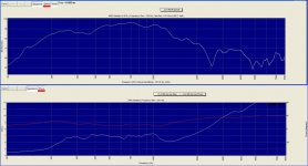
Here is a handy measurement that shows this. This is a ½ volt 2 meter measurement of a part of a large 4 way synergy horn, this would be the raw response of the lower mid section.
In this case the 1w1m sensitivity would be about 115-116 at the peak but the efficiency would be in the 25-40% range (est) so about 10dB of that on axis level is from forward directivity.
Note how the impedance is raised but is also close to resistive through most of the band. As VC heating is I^2*Rdc, this means the electrical power handling is also increased over the direct case.
Best.
Tom Danley
While it is true one can normally ignore the acoustic part, it is also true that the acoustic load can be very visible in an efficient horn system. That acoustic load is a resistance and does show up like one, in fact, if one had a 50% efficient horn, then one would see that the impedance in that frequency range is about twice Rdc and resistive.
Here is a handy measurement that shows this. This is a ½ volt 2 meter measurement of a part of a large 4 way synergy horn, this would be the raw response of the lower mid section.
In this case the 1w1m sensitivity would be about 115-116 at the peak but the efficiency would be in the 25-40% range (est) so about 10dB of that on axis level is from forward directivity.
Note how the impedance is raised but is also close to resistive through most of the band. As VC heating is I^2*Rdc, this means the electrical power handling is also increased over the direct case.
Best.
Tom Danley
Attachments
Has anyone ever attempted to take measurements on a passive 2 way system to see if Le(x) variation from bass is modulating the Q of the low pass filter at the crossover frequency ?
Do you think it would be possible to do this with DC? It would be tempting to upset the output offset of an amp and do a response sweep with +, - and 0 offset, with my current crossover, no crossover, 2nd LP with and without Z comp built in, for example.
I can't see why you couldn't do it with DC.Do you think it would be possible to do this with DC? It would be tempting to upset the output offset of an amp and do a response sweep with +, - and 0 offset, with my current crossover, no crossover, 2nd LP with and without Z comp built in, for example.
No need to mess around with your amp - just connect a large electrolytic coupling capacitor in series with the output (with the right polarity for the DC you're about to apply) and then connect a resistor from an isolated 12v supply to the speaker side of the cap.
Calculate the resistor value to give about 1v or so across the driver impedance. (about 82 ohms for an 8 ohm driver) You should then be able to sweep the frequency response and see if the response near the crossover has changed significantly with +, -, and 0 DC, as you say.
I'd be careful about subjecting the speaker to significant bass excursion with a DC bias applied, it might not be good for the suspension. Just keep the level low and/or only sweep midrange/treble.
Of course DC will only evaluate the shift in frequency response due to impedance changes, it won't give any indication of the level of intermodulation distortion that might also be present with low and high frequencies together, that obviously requires a two tone test with an AC signal at bass and high frequencies.
Last edited:
Regarding the Le(x) and passive crossover Q question, a number of years ago I looked into something like this. The initial purpose of the investigation was to look at the effects of VC heating but it ended up looking like what was observed was Le(x) bebavior. You can view the old web page HERE. When the way back pahe come up click "Impatient " at the bottm, center right of the page.
Further to this, below is a difference curve between a FR sweep on my Delta 15 with and without -4VDC on the VC, crossover in place. (Response dropped with VC displaced inward)
There is obviously something going on beyond a flat loss. How much effect it is having is not clear but there is a very subtle conditional level dependent distortion that I have been trying to track down and this might have something to do with it. FWIW my crossover may not be typical.
There is obviously something going on beyond a flat loss. How much effect it is having is not clear but there is a very subtle conditional level dependent distortion that I have been trying to track down and this might have something to do with it. FWIW my crossover may not be typical.
Attachments
Regarding the Le(x) and passive crossover Q question, a number of years ago I looked into something like this. The initial purpose of the investigation was to look at the effects of VC heating but it ended up looking like what was observed was Le(x) bebavior. You can view the old web page HERE. When the way back pahe come up click "Impatient " at the bottm, center right of the page.
Interesting simulations John, but are you sure about the L(e), R(e) thing? I would swear that you hve the two reversed on your simulated low-pass. The green curve is different only at the crossover point (Q) and that should come from a load resistance shift. The red curve shows the crossover point lowering and that would have to be from load inductance rising.
Note that 60 degree C temperature rising is a lot of input power. We used to inject a little DC through drivers at KEF to measure temperature, and actually had calibrated voice coil temp thermometers that we would take to HiFi shows to show the public. Most of the time they sit at 20 C. Short blasts could get them rising (especially) the tweeter. It takes a lot of sustained high level to raise the steady state temp because you need to raise the magnet structure temp. You can also see the time constants of the VCs and the structures. Tweeter time constant: about 2 secs, woofer 5-10 secs, magnet structures, maybe 10-20 minutes.
Also it should be noted that L(e) does not shift to a new average value with input signal. It modulates with excursion but the mid point is generally constant. As such you can see modulated HF level riding on a big bass note (classic intermodulation), but it should always return to normal when the bass input stops.
David S.
Of course DC will only evaluate the shift in frequency response due to impedance changes, it won't give any indication of the level of intermodulation distortion that might also be present with low and high frequencies together, that obviously requires a two tone test with an AC signal at bass and high frequencies.
If you measure mid band output while shifting static rest position then you have found Bl(x). You then know all there is to know about the AM intermod properties.
Has anybody played with FM detector allignment? Its the same thing. Slope of the S shaped discriminator curve defines upper tone level as swung through the region by a lower tone.
David S.
Interesting simulations John, but are you sure about the L(e), R(e) thing? I would swear that you hve the two reversed on your simulated low-pass. The green curve is different only at the crossover point (Q) and that should come from a load resistance shift. The red curve shows the crossover point lowering and that would have to be from load inductance rising.
Note that 60 degree C temperature rising is a lot of input power. We used to inject a little DC through drivers at KEF to measure temperature, and actually had calibrated voice coil temp thermometers that we would take to HiFi shows to show the public. Most of the time they sit at 20 C. Short blasts could get them rising (especially) the tweeter. It takes a lot of sustained high level to raise the steady state temp because you need to raise the magnet structure temp. You can also see the time constants of the VCs and the structures. Tweeter time constant: about 2 secs, woofer 5-10 secs, magnet structures, maybe 10-20 minutes.
Also it should be noted that L(e) does not shift to a new average value with input signal. It modulates with excursion but the mid point is generally constant. As such you can see modulated HF level riding on a big bass note (classic intermodulation), but it should always return to normal when the bass input stops.
David S.
Hi Dave,
The curves are correct. But as you note changing Le is not the same as Le being a function of excursion. The simulation are just an example of what agrees best with the measurements. The sims suggest that VC heating is not the issue here since changing Re in the sims has a very different result. Changing Le seems to match the measurement better and suggests Le(x) may be the culprit. Yes, Le(x) modulates with excursion, but there would be some RMS value, and remember, the measurement is also an RMS type value. I think the results are pretty conclusive that this is Le(x) behavior. The thing that isn't on the page is that after the discussion at Madisound I when back an tested some higher quality drivers with better motors, namely SS and Seas drivers, and the effect was not present. Then I tested some older drivers including the KEF B110 and the Audax HD13 B25 and there is was again.
- Status
- Not open for further replies.
- Home
- Loudspeakers
- Multi-Way
- Drivers behave as a mass on a spring...