I not have picture, but I install it as close to dust cap as possible, or on the dust cap if possible.Could you show a picture of coin placement? I dont suspect you tape it on next to surrounds.
Cheers!

These days we only need a DVM to measure Re (DC resistance)Hi b_force,
Most DVMs do not respond very high up in frequency. The better handhelds have a -3 dB around 100 KHz, bench up to 300 KHz for most. I would pay attention to your equipment in making measurements. You may know this, but many people not experienced with calibration haven't even looked at the performance data for the meter (or whatever) they are using. People new to this probably aren't even aware of this issue.
Anyway, if making measurements the method I use is extremely accurate, and easy to perform. I did it so often I made up a jig for the purpose.
All other things can be done on an USB audio interface + power amplifier + reference resistor.
Not directly, but indirectly it can be very useful to get additional information about resonances.Is impedance sweep needed if using active crossover at all?
It's also needed to determine the Qt of the system for example.
Last edited:
Too complex, just measure with Arta Limp, and choose analyze. Save borh imp and analyses, done.whether you use the manufacturer provided (Neville)Thiele/(Richard)Small parameters, Advanced Parameter Model, or other models eg. (Wolfgang) Klippel’s suggested Large + Cold models, you can always check your actual tuning frequency with whatever power level you want, using a good old multimeter and a few resistors:
To determine the resonance frequency of the system, set the multimeter to current measurement, then hook it up in series with the subwoofer to your amplifier, then use (a tone) frequency generator to drive the (sub)woofer. At the resonance frequency, the meter will read the lowest result (sealed enclosure) or the highest result (ported and bandpass enclosures)…
… A more accurate version of the above method involves using a resistor in series with the (sub)woofer system, and connecting the multimeter (set to voltage mode) across the resistor. In this case, the meter will measure the lowest voltage at the resonance frequency of a sealed system, and the highest voltage at the resonance frequencies of the ported and bandpass systems.
Reference:
http://www.diysubwoofers.org/faq.html
Section 1.3 1.03 - Tuning - checking the resonance frequency
Courtesy
@Brian Steele
So you get to have your cake and eat it too- model with whatever you have (or nothing at all) and check the tuning frequency with whatever drive level you want (small (voltage) signal, Large signal, driver warmed up, or broken in or not).
So go ahead and drive your (sub)woofer with 0.1V, 1V, 2V, 2.83V, heck 28.3V or 120V (if you dare😂) and check the tuning frequency. Was it close (enough to your simulation?
As with a lot of DIY things; we can all get carried away (we’re not getting paid by the hour, so why stop?).
But having had done this experiment some 20+ years ago, I can attest that the tuning frequency doesn’t sway as much as you might have been led/read to believe.
Yes it changes a bit, but In the grand scheme of things, there are other things to be mindful of, like the woofer excursion going through the roof / Power handling falls off a cliff below the tuning. There’s a real risk of permanently damaging your (sub)woofer if you don’t have a subsonic filter “but I have was 40W amplifier!” but that’s a topic for another day….
Remember that simulations, are, well, sims.
In many fields including sciences and engineering, theoretical models sometimes fail to predict real-world behaviour. The gap that can exist between a clean, idealized model and the messiness of reality is a reminder that practical experience is invaluable and that theories must be tested.
So just a proceed, and build and have fun!
I was thinking the same thing...Hi Hörnli,
Well, why not attempt to explain yourself. It's easy to throw out a comment without anything to back it up.
--- --- ---
Normally I am not a nag about staying on topic, but this subject somehow brings out a lot of strong opinions in people... so I am going to frequently remind people to stay on topic.
I dunno, maybe by using those new-fangled cellphone thingies.. ?But than I wonder how one can communicate on forums like this?
FWIW, I had a simple frequency generator and multimeter long before I owned a computer.The other one requires a scope and a frequency generator?
These days a simple app can turn your phone into a frequency generator.
You'd be surprised how many don't have access to a PC.
Heck, when I started, test equipment was tube (yeah, those hot things that break if you drop them). Computers were on TV and filled rooms. We learned to get the most of our gear, and also learned the limitations of each piece. The 'scope? Triggering? What was that? At least the VTVMs had good high frequency response.
I am suspicious of apps on cellphones. They aren't calibrated or have any guarantee that they do what they are supposed to do with any accuracy. Certainly not what many might expect.
Computers may not be PCs, and you're right. Many don't have access, or have the other hardware to do some of this stuff.
Re Impedance sweep, assuming you can get hold of manufacturer ZMA files. I put this below on axis frequency response measurements.
Box loading will not change impedance where you cross over your drivers. so manufacturer data is fine here for passive modeling.
For box tuning - manufacturer TSP is fine. If you have a vented enclosure you can eyeball the cone minima at tuning frequency given sufficient volume. I've done this to within +/- 2Hz accuracy to any measured impedance dip. VituixCAD will give you a full simulated impedance curve for the driver in the box if you really want it. I've found it very close to reality and perfectly fine for crossover modeling.
I'm not saying impedance sweeps aren't useful... I just put them below actual in box driver on axis frequency response measurements
Multi tone particularly two-tone tests are maybe better than THD tests, I do both.
Two-tone tests are good at showing up IM Distortion. IMD is much more audible and more irritating than THD.
A set of car keys resting on a enclosure with a rub and buzz sweep will show up enclosure harmonics.
A impedance sweep tells a lot about driver inductance. (the slope of the curve) Pick the enclosure size that you want use, the impedance sweep will tell you if the driver resonance will work in the selected box.
I use a QuantAsylum QA403 out in the yard/forest.
I use a Audio Precision analyzer and GRAS microphones indoors.
If you do not have a computer get one.
Thanks DT
I have tested so many speakers in my life. If you really want to get the best out of a system, you simply can't trust manufacturer T/S parameters anymore.For box tuning - manufacturer TSP is fine.
Like I said in an earlier post.
That's not because they are not accurate, but that's because they make up their own way of testing them.
Which can result in horrible performance in actual uses cases.
Room modes are pesky, but they don't change the response of a system.and in any case room modes,
I have seen parameters that shifted well over 20Hz.
Which was clearly audible, even for the biggest audio noob.
In this case we changed the little woofer for a model that didn't have this issue and the problem was gone.
Ever since I am doing poor man's Klippel measurements.
Obviously this is a lot less of an issue with closed box systems with active EQ.
But since this is a thread about what's important for designing loudspeakers in general, context is paramount.
Point is that you just can't blindly trust, let alone compare datasheets from manufacturers.
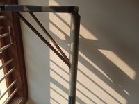
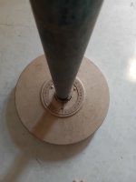
I made this first cut crude build to aid this painful procedure. Has a angle indicator too. Speaker plane will be centred along centre vertical axial pole so can have same distance more or less while I rotate. Next step is to improve this and add PC control and automation.Impedance and frequency response in the ACTUAL CABINET at different degrees.
The hard thing is to keep the distance perfectly the same over wide angles, otherwise phase gives errors ...
Attachments
Missed this bit.IF you don't test a parameter the same way exactly that the published values were obtained, your results are very probably not valid.
But this is the chicken egg story.
Because it assumes that the way the manufacturer tested the loudspeaker is the correct way?
Sure, after emailing back and forth a lot and finally getting the answer what method they used, I get the same results as in the datasheet.
But how is that helpful for comparing datasheets, let alone useful for real world practical use?
That's a rhetorical question, because the answer is that's not helpful at all.
Fyi, like I mentioned before, basic parameters like Fs, Qms, Qes, Qts and Re can already be gained easily without sticking things to a woofer.
Meaning, someone can already very quickly see how far off the measured parameters are compared to the datasheet.
So there can be absolutely no argument be made about lack of accuracy.
Last edited:
Shall we leave the TSP nit-picking behind and move on to much more relevant measuring items?
I have used only sealed boxes, the TSP helps in selecting a driver in combination with the volume, aiming for a Qts of around 0.7 .
This is for me also true for a midrange. With accuton in the past their TSP were way off.
So to summarise, impedance sweep is important to know its behaviour. Not only at Fs but also on resonances, rubbing or other manufacturing errors. Listening to the driver during sweep also to hear any rattling, ticking, or any mechanically created noise.
Since last year i also do imp sweeps at 1, 2.8, 4 V rms to get a baseline for its behaviour at normal usage levels.
Of course i do some breakin at a frequency somewhat below Fs, and with an amplitude like the limited by voice coil height.
And to underline it i listen during those sweeps for audible issues.
If this is all ok, i proceed.
Tools baseline for me: use of tools like Arta(its cost is a no brainer) icm with a decent (usb) audio interface , a dvm for calibration, ( oh, and a computer ;-))
- Home
- Loudspeakers
- Multi-Way
- Driver Measurements Which Are Needed For Speaker Design