Yes, our city apartment is not big at all, it makes a noticeable difference in the living room. Money and time where spent to explore what is a solution I find just right. Maybe I will build a big set with the Faitals and a free standing waveguide sometime later, for the studio or so. The ten-inch form factor is the compromise I was searching for. Also, spending day after day with ath is probably not worth the outcome, in relative terms, it’s just a game to me.
The new version is 70 percent of the size, or a 30 percent size reduction.
0,049 versus 0,070 cubic meters (external).
If spending time building and simulating in ATH doesn't distract you from things you must do, then it's ok - a hobby i share and i do it all the time.
I've just looked ad TS parameters for PHL 3411, and it seems that 10PR320 shares similar features with a little larger Xmech and quite a bit lower Mms. Maybe a good candidate for test if you realize you're not satisfied with PHL's sound.
Last edited:
When it was time to order, the Faital prices where at their all time high, and shortly after, precisely after ordering, almost down to pre-pandemic prices??
The choice to buy a more expensive alternative was easy then and I wanted to test the PHL. After todays changes, I have the impression we could become friends. It also reacts really well in the box, I did not need some of the PEQs that WinISD suggested, and had no need to shelf the higher frequencies to create flat response, the option you had pointed me to at some stage of my driver investigation. The breakup at above 2k is much more pronounced than with the Faital, but is succesfully surpressed and controlled with EQ.
The choice to buy a more expensive alternative was easy then and I wanted to test the PHL. After todays changes, I have the impression we could become friends. It also reacts really well in the box, I did not need some of the PEQs that WinISD suggested, and had no need to shelf the higher frequencies to create flat response, the option you had pointed me to at some stage of my driver investigation. The breakup at above 2k is much more pronounced than with the Faital, but is succesfully surpressed and controlled with EQ.
I will limit this after pandemia, but it was/is nice while it lasted.If spending time building and simulating in ATH doesn't distract you from things you must do, then it's ok - a hobby i share and i do it all the time.
.....
I will limit this after pandemia, but it was/is nice while it lasted.
I hear you.
Pandemia, whew... I almost forgot about that one given what other stuff happened on personal, local and global level. Also living in a small apartment, eyeballing large loudspeakers but using small ones. Moved some smaller bookshelfs into kids room recently and imediatelly planning something larger in our living room. Your writtings, tests and findings will be missed.
Last edited:
Thanks for the kind words. Yes, trial and error with tools is my mode, lacking math skills. Frequently leads to stupid things: The missing mid-range with the PHL, it was not the bass response. Although too much bass can mudden the presentation, it was my misunderstanding of the Moving Mic Method in-room measurement that was much more relevant. The port leakage was very present (+5 dB @650 Hz, Q ~ 3) in the in-room measurement, was wielding the mic about 30+ seconds every time. But I knew that it was not in the anechoic response, because the port is rear facing.
However:
I saw the graph with this big resonance and ... corrected it. When I disabled the room EQ, -4 dB @650 Hz, Q=3, guess how nice the sound became! 😵 I love the PHL 3411 now.
Will take a while till I finish this project anyway, next the waveguide, then the cabinet.
However:
I saw the graph with this big resonance and ... corrected it. When I disabled the room EQ, -4 dB @650 Hz, Q=3, guess how nice the sound became! 😵 I love the PHL 3411 now.
Will take a while till I finish this project anyway, next the waveguide, then the cabinet.
you've probably got it sorted, but i would be careful about using the moving mic method. It averaging measurements in an odd way, because it depends how long you spend in each position. I'd probably recommend doing the measurements individually and averaging using RMS in REW. your probably gonna get much more realistic and useable results. lets you also see where the holes are in the room, and balance that out with more measurmentsit was my misunderstanding of the Moving Mic Method in-room measurement that was much more relevant. The port leakage was very present (+5 dB @650 Hz, Q ~ 3) in the in-room measurement, was wielding the mic about 30+ seconds every time. But I knew that it was not in the anechoic response, because the port is rear facing.
ject anyway, next the waveguide, then the cabinet.
Wow.
Genelec’s Ilkka Rissanen first played a psy-op on me, to persuade the public PHL 3411 is not the woofer that was used in S360A, but some magic 'proprietary' version (sure, as if). And after, when I investigated his claim and asked for a proof, he even threatened to kill me! 🤣
Ilkka Rissanen said:If I tell you, I'd have to kill you. 🙂
Genelec’s Ilkka Rissanen first played a psy-op on me, to persuade the public PHL 3411 is not the woofer that was used in S360A, but some magic 'proprietary' version (sure, as if). And after, when I investigated his claim and asked for a proof, he even threatened to kill me! 🤣
I remember that port position is often discussed, not only port material. Port resonance is a big problem with this box.
This port is 20 cm long (flange to flange), 8 cm in diametere and terminated on both sides. Internally its end is pointed at the baffle between waveguide and woofer, where I had applied some felt. The resonance is really strong and I cannot accept this for the final cabinet.
I can make a second test cabinet, could a different port location mitigate the problem? And what should I look for then?
Even higher in level when baffle step is applied (stupidly not saved measurements to show now)
This port is 20 cm long (flange to flange), 8 cm in diametere and terminated on both sides. Internally its end is pointed at the baffle between waveguide and woofer, where I had applied some felt. The resonance is really strong and I cannot accept this for the final cabinet.
I can make a second test cabinet, could a different port location mitigate the problem? And what should I look for then?
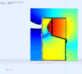
Quessing from the images is it about 10" deep and wide box? This is roughly 25cm and lowest internal mode at half wavelength would be about 650Hz.
If it was pipe resonance this would be tad higher up above 800Hz for 20cm long pipe.
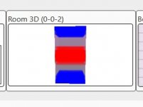
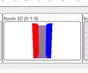
So, it seems to be box mode leaking out. To reduce internal mode leak out change location of internal end of the pipe. You could use room simulator ( scale the dimensions and frequency by ten for it to work) to find where there is null inside the box for 650Hz and try hit that with the end of the tube. Its probably center of the box/dimension for lowest mode. Near wall would be worst possible position, all modes seen there.
You could bend the tube for example, or 3d print a nice elbow or bent tube to hit the spot. It might be hard otherwise as the tube is quite long in comparison to speaker dimensions.
You could also try reduce the mode as soon as possible by placing damping material behind the woofer, but this might not be enough alone. Positioning the inlet is the most effective here, but can be lot of work to find good position and make tube that hits the position.
Last edited:
So, it seems to be box mode leaking out.
This seems to be correct. Which tool shows me the location of the modes at around 600-700 Hz? REW didn't helpt me, it is not in 3D, and I am having no luck with this either https://amcoustics.com/tools/amroc once, but
Not that I can see but you could try this
https://www.audiosciencereview.com/...ency-response-simulation-low-frequency.24850/
https://www.audiosciencereview.com/...ency-response-simulation-low-frequency.24850/
Enlarging the modes is done like so:
If box is 25 x 25cm, multiply them dimensions by ten so input 250cm x 250cm into room mode sim. Scale down your frequency by same factor as well. Problematic mode was about 650Hz in port measurement, so now you are looking at 65Hz mode and its null in the scaled up mode simulation.
Magic of wavelength 🙂
Last edited:
I think he just meant making the picture of the room modes from amroc bigger (as you can enter small values in the boxes directly already without the need to scale).Enlarging the modes is done like so:
I'm not sure, I can't get it to work with tens of centimeters, shows modes that are too low and shouldn't exists in the "room"? Luckily scaling the dimensions is easy enough, append 0 to the dimensions an pop 0 out from the hertz 🙂
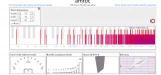
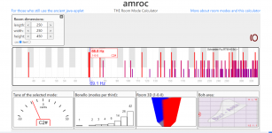
I never used this tool actually, stumbled on it on Finnish forum posted by no other than Kimmosto 😀 I've been imagining the axial modes instead, which is quite simple thinking exercise. Sim gives all the other modes as well, tangential and oblique, which are good to know but not too important with ported boxes. While they are real on ported boxes their pressure nodes are close to walls which we avoid anyway reasoning with the axial modes alone.
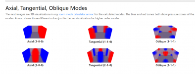
Imagination exercise for axial modes: sound pressure is low at velocity node (anti-node) of a standing wave. Walls have all the pressure nodes and depending on the order of standing wave there is 0, 1, 2 or more pressure nodes somewhere in between as well. From this we reason near wall placement is worst for leaking mids, avoid it. Measurements usually show it is the lowest standing wave, perhaps second lowest as well that came through so position the port inlet avoiding at least the worst of these two, the lowest mode. Good place for inlet is perhaps middle of (problematic) dimension where the velocity node is for lowest mode or perhaps at 1/3 of that dimension if the second lowest standing wave also came through, which has a pressure node on the middle, velocity node on 1/3. Best place for inlet thinking only the lowest standing wave is exactly middle of the enclosure, but if something is leaking through nudge it out from the center accordingly. If (near) center is not practical, at least take the inlet as far out from the walls as possible.
Anyway, this is just simplified reasoning, measurements can confirm if the inlet is in good enough position, not much distinct mid range peaks coming through. There might be complex shape inside the box (like big waveguide or compartment for another driver) and damping material perhaps altering a dimension so it might not be as simple as taking rectangular box/room.
Link to Amroc:
https://amcoustics.com/tools/amroc
ps. be sure to check other tools on the site, very nice for imagination exercises, been using the ray tracing tool alot!😀


I never used this tool actually, stumbled on it on Finnish forum posted by no other than Kimmosto 😀 I've been imagining the axial modes instead, which is quite simple thinking exercise. Sim gives all the other modes as well, tangential and oblique, which are good to know but not too important with ported boxes. While they are real on ported boxes their pressure nodes are close to walls which we avoid anyway reasoning with the axial modes alone.

Imagination exercise for axial modes: sound pressure is low at velocity node (anti-node) of a standing wave. Walls have all the pressure nodes and depending on the order of standing wave there is 0, 1, 2 or more pressure nodes somewhere in between as well. From this we reason near wall placement is worst for leaking mids, avoid it. Measurements usually show it is the lowest standing wave, perhaps second lowest as well that came through so position the port inlet avoiding at least the worst of these two, the lowest mode. Good place for inlet is perhaps middle of (problematic) dimension where the velocity node is for lowest mode or perhaps at 1/3 of that dimension if the second lowest standing wave also came through, which has a pressure node on the middle, velocity node on 1/3. Best place for inlet thinking only the lowest standing wave is exactly middle of the enclosure, but if something is leaking through nudge it out from the center accordingly. If (near) center is not practical, at least take the inlet as far out from the walls as possible.
Anyway, this is just simplified reasoning, measurements can confirm if the inlet is in good enough position, not much distinct mid range peaks coming through. There might be complex shape inside the box (like big waveguide or compartment for another driver) and damping material perhaps altering a dimension so it might not be as simple as taking rectangular box/room.
Link to Amroc:
https://amcoustics.com/tools/amroc
ps. be sure to check other tools on the site, very nice for imagination exercises, been using the ray tracing tool alot!😀
Last edited:
This is relevant also for the woofer position as well. Put it in the middle of dimension and the lowest standing wave is not excited for that dimension. If woofer is on the middle of baffle then the front/back standing wave would be the strongest of the three axial modes, as the woofer is on the end exiting the standing wave maximally while on the middle of the two exciting them a lot less. Keep the box as small as possible and as shallow as possible, woofer on the middle and the internal standing waves are pushed up in frequency, possibly out of band. Could put another woofer on the opposite side to get the front/back lowest standing wave also out, as now the woofers are effectively middle of that dimension as well.
- Home
- Loudspeakers
- Multi-Way
- Driver for JBL 708-ish dimensioned 2-way
