Hi
I am looking a schematich for my next project about a single ended 6C33CB amplifier.What do you think about a 6BM8 (ECL82) for the driver stage ?? or this is a bad idea
thanks
I am looking a schematich for my next project about a single ended 6C33CB amplifier.What do you think about a 6BM8 (ECL82) for the driver stage ?? or this is a bad idea
thanks
The 6E5P is a popular driver and it has worked fine for me.
http://www.goodsoundclub.com/PDF/Melquiades_SET.pdf
If you have not come across it already, you should read Romy's website about the care and feeding of 6C33C tubes.
GoodSoundClub - Romy the Cat's Audio Site - The short "6C33C Survival Guide".
Finally, you might find my parafeed version interesting.
Audio ratbag: Cat Vomit Special - a 6E5P / 6C33C parafeed amp
ray
ratbagp,
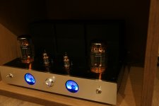
I like your 6C33C SE Parafeed amplifier.
Nice!
Romy's website recommends to only use the 6C33 with fixed bias, says not to use self bias.
And he recommended using less than 100k for the 6C33C grid resistor (fixed bias always requires a lower resistor for the grid, versus self bias).
You used Self bias RC in the 6C33C cathode.
You used 240k 6C33C grid bias resistor.
That combination seems reasonable (because it is operated in self bias mode).
Good job proving that there is more than one way to operate a 6C33C!
Last edited:
In some data sheets for pass tubes, it's recommended that a spec'd minimum fraction of the bias voltage is got through a cathode resistor. I used fixed bias alone with 6336's and quickly learned why.
In the case of power tubes prone to flirtation with runaway, grid chokes can be something to try.
In the case of power tubes prone to flirtation with runaway, grid chokes can be something to try.

Finally, you might find my parafeed version interesting.
Audio ratbag: Cat Vomit Special - a 6E5P / 6C33C parafeed amp
Nice amp -- although your cat seems to think otherwise 🙄
Usually when Kitty decides that something doesn’t smell enough like him/her, urine often comes out instead. If it happens on the bed, you might kill him. On the amp, the amp will. Tends to flow more than vomit and might find the transformer.
High Power SE 6C33C Amp | audioXpress
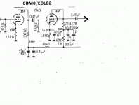
I draw the same schematic with just 1x6c33cb, direct couples all 3 stages.
Here is autobias if you're interested:Усилитель SE 6Н6П+6С33С >> Журнал практической электроники Датагор
I draw the same schematic with just 1x6c33cb, direct couples all 3 stages.
Here is autobias if you're interested:Усилитель SE 6Н6П+6С33С >> Журнал практической электроники Датагор
Attachments
Auto Bias for sure, or . . .
How do you simulate the real world standing current drift of 3 stages that are direct coupled?
Might thermal run-away take over?
How about using Regulated DC filament supplies, Regulated B+ supplies, and Regulated Bias supplies?
"You should make things as simple as possible, but no simpler." Albert Einstein
Just my $2 worth.
Many people built OTL amp, some are direct couples all stages, there are no regulators in there, see Tim Mellow OTL amp and OTL amp is more critical than the SE amp it has no OT to protect the speaker except a spark gap neon at the output. The bias drift is being minimized by the initial burnt-in stage. I think so less reliance on regulator.
Koon,
As to protection circuits in an OTL amplifier . . .
How many volts will cause that 'spark gap neon' to arc over?
How many amps can it take for 20 seconds? (For and example, a 1.5A slow blow fuse in the power supply of the amplifier that is rated to blow after 20 seconds at an overload current of a certain percent beyond 1.5A).
What is the part number of that 'spark gap neon'?
. . . I am really curious to hear all those numbers.
Consider an OTL amplifier that can put out 16 Watts rms into a 16 Ohm speaker.
A sine wave of 16 Watts rms into a 16 Ohm speaker takes 1 Amp rms (1.414A peak).
And, at 16 Watts, the signal voltage is only 22.6 Volts peak.
My reasonably good Mains Power provider, delivers 120Vrms that varies from a low of 117Vrms to a high of 123Vrms,
measured on a true rms meter. And, the crest factor is quite good too.
That is approximately +/- 1.26% voltage range
I do not regulate any of my supplies: B+, AC filaments, DC filaments. But of course, they vary accordingly by the +/- 1.26%
A 3 stage DC coupled OTL that does not use DC offset feedback to get the output offset voltage near zero, then suppose the DC offset is 0.1V into a 16 Ohm woofer, how many mm is the woofer cone displaced from mechanical zero?
Does 0.1V DC offset to the woofer cause additional distortion, and slight loss of dynamic range.
Your, or anybody elses OTL amplifier Mileage and total sound System Performance May Vary, accordingly.
Last edited:
Gas discharge tube (GDT) 90V DC Sparkover in the output.
Part #CG90L Gas Discharge Tube (GDT), 2-Electrode, CG Series, 90 V, Axial Leaded, 100 A, 400 V
https://www.farnell.com/datasheets/2243862.pdf
When one rail gone, the other rail gives offset at output at least 100V DC. Say speaker DC is 8 ohms, 100/8=~12A, the will blow 2A rail/speaker fuses or even 5A fuse AC inlet very quickly. Atma-sphere OTL later model don't even have rail/speaker fuse, only AC inlet fuse nor any GDT in the output, but claim the speaker should be rated at least 8W and above to be safe. As for the DC offset, since gNFB is not DC (via a capacitor) any DC offset will not affect the bias. In fully balance OTL, DC offset (in my amp) is limited to < 2Vp-p, and cut off if exceeded this level. An OTL amp solely relied on gNFB usually has higher DC offset than a well balanced one and with few or no poles is better.
P/S Recently one rail e-cap (200V/1000u) exploded, blown one rail fuse and main fuse, my full range speaker is not damaged.
Last edited:
Koonw,
Ah, now I understand what you are saying. A gas discharge device to protect against large DC voltages caused by any parts failures . . .
Not having anything to do with a working OTL that just has a DCV offset, but not a failure mode.
Still, I do not have any speakers that like dealing with a DC offset of + 1VDC or - 1V DC; or even harder to deal with, that may vary as much as + 2VDC or - 2 volts DC.
High Power SE 6C33C Amp | audioXpress
I draw the same schematic with just 1x6c33cb, direct couples all 3 stages.
Here is autobias if you're interested:Усилитель SE 6Н6П+6С33С >> Журнал практической электроники Датагор
I have this version built (with one output tube and without a cathode resistor - i measure bias on CRC filter resistor and output transformer not grounded). Bias is very stable, nothing floats there. Of course I do not load t the output lamps to the maximum power - but around 40-45 w (205V @ 200mA). Its servs me for years.
6cg7 or 6gu7 -as drivers.
Attachments

Still, I do not have any speakers that like dealing with a DC offset of + 1VDC or - 1V DC; or even harder to deal with, that may vary as much as + 2VDC or - 2 volts DC.
Hi there, of course, that is just the range of speaker cutoff unit when the speaker is supposed to cutoff at (+-2V) when minor fault appears, the actual offset is < 100mV or less. 15 years ago I built an OTL amp that has terrible DC offset, I can see the woofer breathing... not anymore as development advanced.
Hi there, of course, that is just the range of speaker cutoff unit when the speaker is supposed to cutoff at (+-2V) when minor fault appears, the actual offset is < 100mV or less. 15 years ago I built an OTL amp that has terrible DC offset, I can see the woofer breathing... not anymore as development advanced.
- Home
- Amplifiers
- Tubes / Valves
- Driver for 6C33C