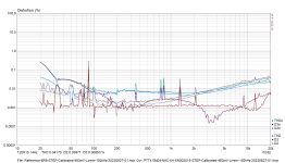
It's a closed box speaker, connected once through a 20 ohm resistor, then directly to the amplifier. The impedance plots are self-explanatory.


The distortion measurement shows the harmonics in the current to the speaker. Once connected via the series resistor, then directly on the amplifier in the overlay.

Have you ever measured current distortion on a loudspeaker?
The distortion measurement shows the harmonics in the current to the speaker. Once connected via the series resistor, then directly on the amplifier in the overlay.
Have you ever measured current distortion on a loudspeaker?

I have.
What would interest me greatly is the opportunity to build drivers designed for active current mode amplification. Who cares if the impedance varies if the amplifier will handle it anyway? They could focus on reducing all distortion products that are not reduced by using a current signal. But then the other side of the coin is that manifacturers would have to start producing current mode amplifiers.
The most sad thing is that current mode amplifiers do exist, they just won't sell them to us but there are companies they use them for themselves. The Grimm LS1 uses current mode amplifiers. I think I read somewhere that the Apple Earpods used current amplification too. The Designer of the Purifi (same guy that designed the Hypex NCore and the Grimm LS1) was asked about designing a current mode version of their amplifier and selling it but answered that they wouldn't because then even non Purifi drivers would perform almost as good as the Purifi drivers (whose drivers have well built, huge and expensive magnets to mitigate current distortion).
Here is an example of a pretty good driver that has shorting rings. https://www.diyaudio.com/community/threads/any-current-mode-class-d-ics.379267/post-6843553 Not a huge difference but there is a difference. Here are some more drivers that benefit to a varying degree from current amplification: https://www.diyaudio.com/community/threads/hypex-ncore.190434/post-4095122
Last edited:
Looking at your measurements of the impedance, which one is the one with 20ohms in series? If i understand what you stated, the upper one. Same for distortion, rhere it appears the current driven distortion is higher, correct?@>JanRSmit<
Thank you for your question about the measurement setup and a sketch. Here you are. I hope the sketch covers your interest.
Feel free to ask. View attachment 1206397
Just an experiment with the 0.135Ohm rig for imp-meas i used for distortion measurment acros the 0.135Ohm resistor thus current distiortion.
THe amp output voltage is 2.83V rms
The connection with the Scarlett2i2 is with unbalanced line-input, but calibrated (~483mV rms)
The Overlay data is the measurement of a TT4.0M04-NAC-04, the other is measurement of a 6R8 resistor.
Still learning ARTA-STEPS and its configuration.
Never the less interesting
Attachments
@>OllBoll<
Thank you for your answer to my question.
If you like, show and explain your measurement.
Feel free to ask about "drive current distortion measurement".
Thank you for your answer to my question.
If you like, show and explain your measurement.
I will not jump to any conclusion.Who cares if the impedance varies if the amplifier will handle it anyway?
Feel free to ask about "drive current distortion measurement".
Last edited:
@>JanRSmit<
It's not easy to read measurement diagrams. Thank you for bringing this to my attention.
When looking at my measurement diagram for many hours, a visual mnemonic has formed for me. My visual perception now sees three pairs of curves. Each pair is similar in shape. For example, the shape of D3 resembles the shape of the overlay D3o. I tried to enhance this effect with similar colors. The darker color in a pair is the overlay and thus the curve without the 20R resistor, i.e. directly on the amplifier.
Regarding my impedance plots:
Look at the Y-scale on the left of each of the two impedance diagrams. The scale shows Z in ohms. This makes it clear which diagram is which
I would like to look at your measurement a little longer before I go into it.
@>JanRSmit<
I just found the thread you started last year ...great.
So my remarks here will be short.
We had the same approach:
 I tend to come across as showing off. I'm sorry.
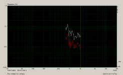
This is a 8R25 in place of the Loudspeaker. Again with and without 20R resistor. I have similar spikes.
This remarks me about cancelling less useful plots next time, as i did in the opening post to D4/D4o. D4 was so noisy that it was like a curtain.
Luckily I managed not to destroy my 2i2, but I hit the diode limiter several times, please be careful. The diodes are 2N4004.
Ask me any question regarding ARTA. I will at least try to be helpful.
How did you do the calibration? Multimeter? I have to admit there was no calibration at work with my measurements.
I just found the thread you started last year ...great.
So my remarks here will be short.
the other is measurement of a 6R8 resistor.
We had the same approach:
I tend to come across as showing off. I'm sorry.This is a 8R25 in place of the Loudspeaker. Again with and without 20R resistor. I have similar spikes.
This remarks me about cancelling less useful plots next time, as i did in the opening post to D4/D4o. D4 was so noisy that it was like a curtain.
Luckily I managed not to destroy my 2i2, but I hit the diode limiter several times, please be careful. The diodes are 2N4004.
Ask me any question regarding ARTA. I will at least try to be helpful.
How did you do the calibration? Multimeter? I have to admit there was no calibration at work with my measurements.
Last edited:
My answer risks endless discussion. I have had extensive experience on the internet on this subject since 2004. I am fully aware that you probably have more intelligent interests than my short answer can satisfy. So I would like to ask you: please ask.Hornli, did the two measurements ( one with and one without the 20R resistor) produce the same SPL output from the speaker?
For the same voltage at the amplifier output, the 20R resistor results in a current level that is about 10 db lower. So the voltage at the amplifier output was raised by about 10 db in order to have at least a very similar current level in both measurements. The level of the sound pressure depends immovably on the level of the current. Now: please ask!
The question was clearly about SPL - not volt or amp.
"Hornli, did the two measurements ( one with and one without the 20R resistor) produce the same SPL output from the speaker?"
Why did you need to complicate things? Or describe your internet skills? And you managed ro not answer the question actually... try again. Make it simple. Yes or no.....
//
"Hornli, did the two measurements ( one with and one without the 20R resistor) produce the same SPL output from the speaker?"
Why did you need to complicate things? Or describe your internet skills? And you managed ro not answer the question actually... try again. Make it simple. Yes or no.....
//
The large sense resistor is likely influencing the measurement results.It's a closed box speaker, connected once through a 20 ohm resistor, then directly to the amplifier. The impedance plots are self-explanatory.
View attachment 1205843 View attachment 1205844
The distortion measurement shows the harmonics in the current to the speaker. Once connected via the series resistor, then directly on the amplifier in the overlay.
View attachment 1205845
Have you ever measured current distortion on a loudspeaker?
Thanks TNT. Looks like the answer is there (I think), if a little burried. My intention is to learn, Hornli, and I am well aware of this phenomenon. In fact, I am playing around with high output impedance amps and current source crossovers.
So, looks like the SPL was matched for the two cases, which would indicate dramatic improvement. The problem I am encountering is that when you raise the output impedance, you have to produce more voltage for a given SPL. Some amps hit the rails on material with large dynamic range. Can be heard as gross distortion. So, it requires a bit of thinking and redesign to achieve proper results.
So, looks like the SPL was matched for the two cases, which would indicate dramatic improvement. The problem I am encountering is that when you raise the output impedance, you have to produce more voltage for a given SPL. Some amps hit the rails on material with large dynamic range. Can be heard as gross distortion. So, it requires a bit of thinking and redesign to achieve proper results.
Hello All,
This is the setup that I use. The resistor is 0.1R.

It is the setup that is internal to the Audio Precision APx1701 transducer test interface. The sense resistor is small compared to the driver impedance on purpose to minimize the resistor's effect on the circuit.
Thanks DT
This is the setup that I use. The resistor is 0.1R.
It is the setup that is internal to the Audio Precision APx1701 transducer test interface. The sense resistor is small compared to the driver impedance on purpose to minimize the resistor's effect on the circuit.
Thanks DT
I would like to suggest to start deleting graphs without interest. I would suggest showing only D3 and D3o at first. Please measure the transducer and the 6R8 again. Please show the measurement here.Still have to find a solution to deal with the spikes. Any idea?
Bruno Putzeys never said this!but answered that they wouldn't because then even non Purifi drivers would perform almost as good as the Purifi drivers
Your measurements were used in a German forum as proof for not working distortion reduction by using a resistor. As any measurements in the sound pressure domain this measurements are massively flawed by:
The distorting microphone (D2 tracks sound pressure)
Noise hiding D4 and higher
Poor equalization
I did it, I know it, been there to great length...
But you measured it. And your microphone measurements do in part show the reduction of D3 by resistor. Just as mine. See attachment.
Attachments
Last edited:
Buy or rent a Klippel NFS!I'm not entirely convinced. A proper SPL measurement would would have been prudent and more scientific - now it was a proxy test/answer...
or
Buy or rent a really big anechoic AND quiet facility
or
Buy or rent a microphone without distortion
But:
Do it yourself!
Hint: The Klippel NFS does it with microphone distance, to cope with the microphone, and software based elimination of the room reflections.
- Home
- Loudspeakers
- Multi-Way
- Drive Current Distortion Measurement