Sorry, the Power supply problem is just a heat problem and would have failed further down the line. There was a more fundamental problem with CH2, which I finally traced to a short (80ohms) between the 15V power rail and the CV test point for CH2. Turned out after removing connecting board and the resistor from the CV point that it was a short in the connector. Unsoldered, cleaned, check components all ok now, so who knows what caused the short. But obviously the valve heater cct has heat problems. It heats 4 off ECC822's in Parallel
So in summary you have all been very helpful. I'll look into using your ideas to alleviate the heat problem....
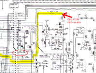
(None of this is helped by Drawmer not allowing circuit diagrams & service manuals to be shared/brought.....Not as if current design, and I'm sure anyone could reverses engineer it without a diagram.....)
So in summary you have all been very helpful. I'll look into using your ideas to alleviate the heat problem....
(None of this is helped by Drawmer not allowing circuit diagrams & service manuals to be shared/brought.....Not as if current design, and I'm sure anyone could reverses engineer it without a diagram.....)
Attachments
Now we know more...so 4 x ECC82. That is 4 x 12.6V 150 mA. That is 12.6V 600 mA in total. This means you could replace the old 7812 for 2 new ones and have ach 7812 feed tubes and halve the dissipation per regulator.
You see... it all depends on what the OP tells us.
You see... it all depends on what the OP tells us.
Now as detailed as I try to help out so vague is your feedback regarding what you exactly did to fix it (I guess: cheapest solution 78S12, removal of D12 and R6, a new 2200 uF cap and the FLIR in the drawer 🙂).
its all back as it was, but with 78S12, and high wattage R6. I tried it just without R6, and it seemed to work fine, but of course will have twice the current flowing through the 78S12, hence heatsink gets warmer....
I think your solutions ref LDO,reducing volage,removing diode and R6 all have merit.
So many thanks
Last edited:
R6 is plain stupid by design as one compromises the performance too and one needs both R6 and the D12 both adding heat nearby electrolytic caps. Effectively nothing has changed for the better. Error by design happens but repeating the error should not happen. Repairing like this means the failure will repeat itself. Sorry.
The total amount of Watts won't change. If it's not the regulator then it's the resistor creating the heat. Divide the power over 2 x 1 Euro 7812 regs and each dissipates half.
Anyway I have suggested many simple methods to improve matters. Cheap always wins, alas. A cheap improvement with single 78S12 is to still add a resistor 2.2 Ohm 5W before the 1N4002. I recall you have 17.2V so you could play with dividing dissipation. With a 3300 µF cap and a 2.2 Ohm it is already solved.
Last edited:
I like your suggestion of the MIC29300-12WT best. So ta muchly....
From someone on eevblog forum....on resistor sharing the pain....
"At one time it was reasonably common to see 78xx regulators bypassed by a resistor to carry more current. In particular it was done in the Amplifone vector monitors on the HV board, and the Heathkit GC-1000 "Most Accurate Clock". At the time I don't think the higher current 3 terminal regulators existed, and also a ceramic power resistor can safely run at considerably higher temperature than a semiconductor. If you're going to dissipate the power, there's some reasonable logic in doing so in a part that can run very hot without problems."
Yes I suggested exactly the same but in a IMO more clever way than repeating completely unnecessary outdated bad habits (solely created because regs were not able to deliver more than 1A many decades ago) in 2021. The power resistor with heatsink mounted against the chassis before the rectifiers/regulator. There where heat doesn't harm.
The manufacturer probably could have chosen a higher rated regulator or "cheap" which is a second 7812. He choose "cheapest": a single 7812 for feeding 4 filaments totalling 0.6A and saved the 75 Eurocent an extra 7812 and a decoupling cap would have cost. Bravo!
The manufacturer probably could have chosen a higher rated regulator or "cheap" which is a second 7812. He choose "cheapest": a single 7812 for feeding 4 filaments totalling 0.6A and saved the 75 Eurocent an extra 7812 and a decoupling cap would have cost. Bravo!
Last edited:
Note that diodes on pcb's such as that have a limited ability to conduct heat away from the die as the diode leads are quite short before transferring to the pcb traces at each end. Conducting heat away is a lot more effective than relying on convection, and the effective thermal resistance of such a diode is very sensitive to lead length and cooling.
Swapping to a diode with lower on-voltage can certainly help. What can be easier is to add an overlay wire on top of the diode's pcb traces, so that heat is better conducted away from the pads via the wire overlay (and likely to cooler climates). That not only reduces diode die temp, but also pcb pad temp and hence long term nearby pcb heat stress.
The same thermal alleviation scheme can also be applied to that bypass resistor.
Last edited:
Yes you could use new 1N4002 and mount them 10 mm from the PCB. They will dissipate just as much as they did before. That is cheap.
You can use Schottky diodes and practically eliminate the issue. That is best.
Cheap = not best
You can use Schottky diodes and practically eliminate the issue. That is best.
Cheap = not best
Last edited:
I'm getting the impression you don't like "cheap" 🙂. (Mind you Schottky diodes and LDO's aren't really expensive....)
The power resistor with heatsink mounted against the chassis before the rectifiers/regulator. There where heat doesn't harm.
has two 15V windings from the transformer to two seperate diodes. So in this case it would be better to put the resistor in series AFTER the diodes, otherwise I'd need two resistors? (ie before regulator)
I'm getting the impression you don't like "cheap" 🙂. (Mind you Schottky diodes and LDO's aren't really expensive....)
No, one could look for "best" and then decide what the best price/quality ratio is of all possibilities. Sometimes the best solution is even free, often not seen when one is busy with cheap/least effort. It can be done better even without having an expensive FLIR that proves nothing has changed 🙂. Repeating existing design errors is an insult to intelligence.
It is comical that you tell me that Schottky diodes and LDO are not expensive when you don't use either of them 😀 Anyway, good luck with all.
Last edited:
- Home
- Amplifiers
- Power Supplies
- Drawmer 12V Valve heater circuit