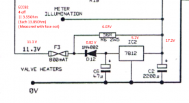
Can anyone please enlighten me as to the purpose of the 2W 56ohm resistor in this cct? (The LED illumitators also have a 2W56ohm resistor in series)
Also IN4002's getting pretty warm, would a higher wattage diode help?
Obviosly 7812 is maxxed out, especially when tubes are cold (heater resistance I believe are 15ohm cold, 80ohm hot)
Also IN4002's getting pretty warm, would a higher wattage diode help?
Obviosly 7812 is maxxed out, especially when tubes are cold (heater resistance I believe are 15ohm cold, 80ohm hot)
Attachments
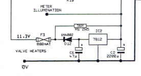
as you noticed, the heater resistance on a cold valve is very low. This can trip the max current detector in the 12V regulator, which therefore never "starts". The 56R is a path for initial current to flow, at certain point the 12V regulator kicks in and regulates the output.
many thanks, that clears it up in my mind
other person on eevblog said something very similar
"The resistor is there to reduce the dissipation of the 7812 by acting as a bypass for some of the heater current (but not enough that it doesn't still regulate the voltage). It probably makes the difference between being able to get away with a 7812 or not at startup.
The 1N4002 is rated for 1A at 75'C ambient. The 7812 is capable of a bit more than this before going into current limit, but unless the 4002 is running really hot, it's probably fine. At 1A it will be dissipating about 1.1W but into 80R load it should be way less than that. You could go to a 3A 1N5402 if you wanted, but it has larger body size and more importantly, thicker leads."
"Cheaply" is the correct word. It is simply outdated/bad practice done for the wrong parameter when applied today. Today one could have chosen the right rated part straight way. Don't understand me wrong, it was done in the past as there was no other choice than 78xx which are 1A limited regulators not able to cope with low cold resistance filaments. Let's forget the habit.
To reduce the heat one could remove the 56 Ohm resistor, remove the diode and use a jumper wire instead, choose an LDO and drop voltage before the regulator if that is necessary. A MIC29150-12WT will be able to pass 1.5A, a MIC29300-12WT will be able to pass 3A. I would choose the latter. For now the most interesting is how many Volts are at the input of the 7812. It would also be beneficial for tube longevity as 11.3V is too low for 12.6V filament tubes. 12V would be OK.
All this for 3.61 Euro.
The caps look like goners.
Last edited:
A MIC29150-12WT would be a good choice when the current draw is way below 1A in normal operation. This regulator will limit the maximum current through the filaments at power up to 1.5A. If that does not work out (apply, test, measure... always!) then MIC29300-12WT is a good choice. All a bit academic compared to AC fed filaments connected straight to a transformer winding 🙂
Last edited:
Thank you Jean Paul, I kind of came to the same conclusion ref resistor and diode. Good to have it confirmed. I have put in a L78S12 which does 2A.
Some people have implied that the 11.3V gives more distortion, I can't see it having much effect at all. It would limit the number of electrons generated, but I can't see it being many....
I put diode and resistor back, Interestingly the regulator drops out every so often, if for instance I measure the voltage on its o/p.
78S12 can be done when it needs to be cheap but it is not an LDO. If you want the current and less heat dissipated by the regulator (better said: divided heat) use the tube guy method for all problems 🙂: voltage dropping. Before the regulator with a chassis mount resistor. Can't advice on using wrong filament voltages, a 12.6V filament needs 12.6V. but allows 12V for somewhat longer tube life. The circuit you have shown may be designed by a divine entity but it is hampered by 4 to 5 design errors.
1. How much Volts are there at the input of 7812? This can be a factor for choices.
2. What about C2? China's cheapest? Also has taken heat. Replacing for a 3300 µF would be good practice. If it's on its way out that may explain the regulator dropping out.
3. You could have a look in your parts stash and replace the heatsinks of the 15V regs to types with longer vertical fins. Less heat is better for caps.
4. Schottky diodes will result in lower heat.. but higher voltage. Is this a benefit or a curse?
Last edited:
17.2V, weird tho I've seen i/p voltage at around 19V...
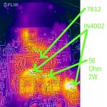
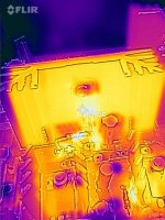
But steady state attached.
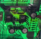
Also heat map without resistor.
Without diode would get hotter? (no voltage drop across diode)
Would be difficult to get resistor in, unless I put before the rectifing diodes (A pair of IN4002's) AC tho - 0.64Ax4,2V to get down to 13V is still best part of 3W. (6.56Ohms?)
But steady state attached.
Also heat map without resistor.
Without diode would get hotter? (no voltage drop across diode)
Would be difficult to get resistor in, unless I put before the rectifing diodes (A pair of IN4002's) AC tho - 0.64Ax4,2V to get down to 13V is still best part of 3W. (6.56Ohms?)
Attachments
2) I've replaced Capacitator, same value, but I hope better quality.7
2. What about C2? China's cheapest? Also has taken heat. Replacing for a 3300 µF would be good practice. If it's on its way out that may explain the regulator dropping out.
3. You could have a look in your parts stash and replace the heatsinks of the 15V regs to types with longer vertical fins. Less heat is better for caps.
4. Schottky diodes will result in lower heat.. but higher voltage. Is this a benefit or a curse?
3) They don't seem to get overtly hot (Hang on maybe they do.... picture before anything changed)
4) que sais.... .... Are you suggesting change the two IN4002 rectifying resistors to Schottky's? intriguing, I could tap off to a resistor at that point I suppose….
Attachments

Last edited:
5. 17.2V, weird tho I've seen i/p voltage at around 19V... This could mean the cap being flaky
6. Without diode would get hotter? (no voltage drop across diode). If you mean D12 yes that one should go when R6 is removed. Then D12 won't generate heat anymore, its part then goes to the tubes 😉
7. Would be difficult to get resistor in, unless I put before the rectifing diodes (A pair of IN4002's) AC tho - 0.64Ax4,2V to get down to 13V is still best part of 3W. (6.56Ohms?). That sounds right, yes before the rectifiers. Make that a 3.3 or 4.7 Ohm resistor of the right wattage. Those chassis mount resistors in heatsinks seem a good choice to get rid of the heat.
8. In this case I would use Schottky diodes to have less heat by the diodes as I would be dropping voltage with the 4.7 Ohm somewhere else anyway. The trick is to divide dissipation and get rid of it to spots where it can't hurt.
9. Please note that when going LDO it makes sense to have less ripple (why? Please think of why). The 3300 or even 4700/25/105 was therefor suggested.
Attachments

Last edited:
many thanks, and
1) advice on "standard" Schottky replacemnets for the IN4002's? 🙄
2) Could I put resistor before the recitifing diodes to reduce the voltage.... ie straight after the transformer..... I think not, just checking....
1) advice on "standard" Schottky replacemnets for the IN4002's? 🙄
2) Could I put resistor before the recitifing diodes to reduce the voltage.... ie straight after the transformer..... I think not, just checking....
Last edited:
Maybe that is something you should engineer?! 1N4002 has 1.1V Uforward so maybe aim for half?
Last edited:
hot diodes have much less forwards drop, both si and schottky's. you can find som high voltage diodes with higher forward voltages, but always check the datasheet at what current.
We calculate worst case and the OP needs lower Uforward for less heat. Please have a look at the FLIR pictures what causes heat.
Since both Si and Schottky diodes have lower Uforward when hot there is no debate nor a show stopping phenomenon don't you agree? Which one of the 2 will generate less heat?
Since both Si and Schottky diodes have lower Uforward when hot there is no debate nor a show stopping phenomenon don't you agree? Which one of the 2 will generate less heat?
Last edited:
actually I have used that effect to limit the dissipation in schottky's for wireless charging of implants by allowing them to heat up, by reducing the thermal coupling. this at the acceptable cost of more reverse leakage current.
That is the answer to an unasked question while the answers to the questions that were asked are not given 🙂
your right of course... If you don't understand what your doing then stop it
anyway it lives, inital problem fixed, and the 19V was caused by a, would you believe it,😱 a dodgy fuse...., the 19V is the output from the transformer with no load....
Thanks for taking the time to point me in some useful directions....
anyway it lives, inital problem fixed, and the 19V was caused by a, would you believe it,😱 a dodgy fuse...., the 19V is the output from the transformer with no load....
Thanks for taking the time to point me in some useful directions....
9. Please note that when going LDO it makes sense to have less ripple (why? Please think of why). The 3300 or even 4700/25/105 was therefor suggested.
Off the top of my head, the whole purpose of the LDO is to be able to regulate with a smaller i/p and o/p difference. Normal regulators need > 2.5V difference, LDO's 500mV or lower. If large ripple and i/p voltage only 500mV different to regulated o/p then oscillations will occur? (If that’s what they mean by oscillations)Larger capacitator irons out difference in voltages generated from transfomer.
Probably total rollocks 😕, maybe I need to google it....
With LDO one tries to keep the difference between input and output voltage at around 1V in general. If the cap is standard value then the ripple voltage might cause the regulator going below its minimum dropout voltage and it will go unstable/do strange things. Upping the cap value is alsmost mandatory and combined with the more expensive regulator this means we will be stuck answering tube guys 78xx and LM317 issues for the next 40 years 😀
Now as detailed as I try to help out so vague is your feedback regarding what you exactly did to fix it (I guess: cheapest solution 78S12, removal of D12 and R6, a new 2200 uF cap and the FLIR in the drawer 🙂).
Now as detailed as I try to help out so vague is your feedback regarding what you exactly did to fix it (I guess: cheapest solution 78S12, removal of D12 and R6, a new 2200 uF cap and the FLIR in the drawer 🙂).
Last edited:
- Home
- Amplifiers
- Power Supplies
- Drawmer 12V Valve heater circuit