Folks, take a look at figure 3 here:
http://www.dself.dsl.pipex.com/ampins/discrete/discrop.htm
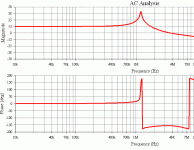
Douglas Self claims 6ppm THD+N at 1KHz , (fig. 4), for his discrete op. amp., but simple AC analysis in spice shows there is no way he could have swept stimulus across the audio band into this design, as it would have certainly broken into violent oscillation along the way...

Attachments
Konnichiwa,
What did you expect? Did you ever get a chance to "fix" on of his mixer designs and I am talking about basic groud routing on the channels and the bus here, nothing fancy....
Sayonara
mikek said:
Douglas Self claims 6ppm THD+N at 1KHz , (fig. 4), for his discrete op. amp., but simple AC analysis in spice shows there is no way he could have swept stimulus across the audio band into this design, as it would have certainly broken into violent oscillation along the way...
What did you expect? Did you ever get a chance to "fix" on of his mixer designs and I am talking about basic groud routing on the channels and the bus here, nothing fancy....
Sayonara
The point here is, if its completely impossible to run this design without oscillation, then the THd+N graph caould not possibly have been obtained legitithemately.... ....the whole thing stinks.....makes one wonder....are those THD curves in his book worth the paper they are printed on????
moderator....i have attached image!
 ....the whole thing stinks.....makes one wonder....are those THD curves in his book worth the paper they are printed on????
moderator....i have attached image!
Attachments
hi Mike.
I did a sim this morning at home, with 2sa970,2sc2240..
Yes it is unstable, but i ended up with a peak at around 7MHz, and a phaseshift much more normal than yours..... I only got a posetive phaseshift not the one you have shown with two shifts!?
Are you sure...... I am not shure that your phaseshift is ok.... sorry. I double checked my circuit twice..
By the way... The highest harmonics was 123dB down. So i would suspect that he could have measured it... I could easily sim it. It only shows unstability when subjected to a squarewave, ringing but it dies out...
Like to hear you answer...
A fix could be rasing the noise gain at high frequencies.... 33pF between the noninverting and the inverting input!?!?
Sonny
I say don't draw conclusions too fast. As Walter Jung points out you must do a follow up with real life circuits. Be positive Mike K 

Mikek,
you better sometimes build than only simulate. Simulation often does not give good results at high frequencies (my experience). The real life is not the simulated one ...😉
you better sometimes build than only simulate. Simulation often does not give good results at high frequencies (my experience). The real life is not the simulated one ...😉
Since Douglas Self doesn't seem to have specified the transistor types he used, it is unclear to me how you can check the stability or the distortion of his design, either by simulation or by measurement. Both stability and distortion may be strongly dependent on the actual transistor types used.
[Douglas Self claims 6ppm THD+N at 1KHz , (fig. 4), for his discrete op. amp., but simple AC analysis in spice shows there is no way he could have swept stimulus across the audio band into this design, as it would have certainly broken into violent oscillation along the way... [/B][/QUOTE]
----------------------------------------------
Any sonic advantage of ppm distortion seems to me to be negated by the two coupling caps he uses
 [/B][/QUOTE]
----------------------------------------------
Any sonic advantage of ppm distortion seems to me to be negated by the two coupling caps he uses
In case that capacitor coupling has cut-off frequency (-3dB) somewhere between 0.1Hz and 1Hz, speaking about foil capacitor distortion is only a superstition.
i have forgotten to say. My sim is with perfect caps and a zero generator impedance. with a impedance of source is 1k the distortion will most likely go up to around the 6ppm.....
peranders said:I say don't draw conclusions too fast. As Walter Jung points out you must do a follow up with real life circuits. Be positive Mike K
PMA said:Mikek,
you better sometimes build than only simulate. Simulation often does not give good results at high frequencies (my experience). The real life is not the simulated one ...😉
.....built the circuit...pretty simple really 30 minute job!....very unstable......as confirmed by calculation...and simulation...

....peaking due to second stage complex pole....miller cap has to be increased to 47p...or there abouts to effect usefull stability...

MarcelvdG said:Since Douglas Self doesn't seem to have specified the transistor types he used, it is unclear to me how you can check the stability or the distortion of his design, either by simulation or by measurement. Both stability and distortion may be strongly dependent on the actual transistor types used.
zetex 'e-line' ztx694 and ztx956....negative feedback should make component differences largely neglegible anyway..
sonnya said:hi Mike.
I did a sim this morning at home, with 2sa970,2sc2240..
Yes it is unstable, but i ended up with a peak at around 7MHz, and a phaseshift much more normal than yours..... I only got a posetive phaseshift not the one you have shown with two shifts!?
Are you sure...... I am not shure that your phaseshift is ok.... sorry. I double checked my circuit twice..
By the way... The highest harmonics was 123dB down. So i would suspect that he could have measured it... I could easily sim it. It only shows unstability when subjected to a squarewave, ringing but it dies out...
Like to hear you answer...
A fix could be rasing the noise gain at high frequencies.... 33pF between the noninverting and the inverting input!?!?
Sonny
Multisim is optimesed for work up to RF..something most gneralpurpose simulators are not capable off......try zetex e-line BSIM3 models....
sonnya said:hi Mike.
I did a sim this morning at home, with 2sa970,2sc2240..
Yes it is unstable, but i ended up with a peak at around 7MHz, and a phaseshift much more normal than yours..... I only got a posetive phaseshift not the one you have shown with two shifts!?
Are you sure...... I am not shure that your phaseshift is ok.... sorry. I double checked my circuit twice..
By the way... The highest harmonics was 123dB down. So i would suspect that he could have measured it... I could easily sim it. It only shows unstability when subjected to a squarewave, ringing but it dies out...
Like to hear you answer...
A fix could be rasing the noise gain at high frequencies.... 33pF between the noninverting and the inverting input!?!?
Sonny
Multisim is optimised for work up to RF..something most general-purpose simulators are not capable off......try zetex e-line BSIM3 models....i have built it...and it is still unstable...just as predicted...
Mike K, what did you want to prove really? If 22 pF = oscillations and 47 pF = stable, so what. You didn't know which transistors Douglas did use so how much value has your critic? Be positive instead! I see Douglas circuit as an example of a design. Be positive!
peranders said:Mike K, what did you want to prove really? If 22 pF = oscillations and 47 pF = stable, so what. You didn't know which transistors Douglas did use so how much value has your critic? Be positive instead! I see Douglas circuit as an example of a design. Be positive!
hi per...🙂
....not trying to 'prove' anything.....just wanted to find out whether anyone could reproduce Self's results as given.....there is nothing 'positive' about an amplifier that oscillates..... 🙄
Now...of course we do not know what transistors Self used.....but this misses the point entirely...because the stability of this circuit is not dependent on transistor type, as Self himself observes....see also....:
http://www.national.com/an/AN/AN-A.pdf
...if we are to understand that his THD+N curve was produced by the circuit as given, then we are perfectly entitled to ask how...wouldn't you agree?
peranders said:Mike K, what did you want to prove really? If 22 pF = oscillations and 47 pF = stable, so what. You didn't know which transistors Douglas did use so how much value has your critic? Be positive instead! I see Douglas circuit as an example of a design. Be positive!
...another point peranders....with 47pF miller compensation, you would obtain more than 0.01% THD+N at 20KHz...no where near the claimed performance....are'nt we entitled to know why?
- Status
- Not open for further replies.
- Home
- Amplifiers
- Solid State
- Douglas Self op. amp. problem..

