Well, what can i say, apart from being too confident and not checking continuity of the hand wired cables when they were finished.
I as many have used Connector Housings e.g. http://uk.farnell.com/harwin/m20-1060200/housing-crimp-receptacle-2-54mm/dp/865606?ost=865606&ddkey=http%3Aen-GB%2FElement14_United_Kingdom%2Fsearch along with the female crimp contacts e.g. http://uk.farnell.com/harwin/m20-1180042/crimp-socket-gold-22-30awg-pk100/dp/1022219?ost=1022219&ddkey=http%3Aen-GB%2FElement14_United_Kingdom%2Fsearch Even though i did not crimp the cables, and had actually preferred to have carefully solder them, what i didn't obviously do was to ensure that the female crimp contacts were pushed firmly home in the housings, so that their latches locked them in place and were not pushed up in the housings.
So i have solved the problem of (with thanks to many) and now have the Left and Right Input pcb's working.
Next to do?
Wire up the MM/MC phono pcb and to use the Cct Mooly kindly send. I hope things go well!
By the way the LED on the Front Panel pcb indicating the LLL levels should be mounted to be viewed as too the 'Power On' LED?
This project has given many problems, circuit/pcb errors, components becoming unavailable etc., yet people are still interested in building it even in 2018.
Because of this Elektor, should provide a complete rewrite/reprint of this project and to have the complete circuit viewable for us all!
It's an embarrassing May 2018, but i'm closer to finishing my Elektor Preamplifier, but at least i have the superb Elektor Q-Watt running daily for many hours.
Its great to get opinions and assistance from you all, with thanks
calpe
Last edited:
Good job and a lot of tenacity on you part. Sorry, I haven't been around much. Been preoccupied with life and other things. It's easy to become over-confident. When we do, we/I make mistakes. Projects like this - at least for me - requires a certain degree of attention to detail! But that's just me. Now you can start to enjoy it.
Rick
Rick
It's not quite finished, as i now need to connect up the Phono pcb, with extreme care!!!
Sadly, this project leaves a lot to be answered by the Elektor magazine, it lacks so much information and guidance, let alone the errors i found.
When completed i plan to use it with my Elektor Q-Watt power amp.
Cheers to you all
Sadly, this project leaves a lot to be answered by the Elektor magazine, it lacks so much information and guidance, let alone the errors i found.
When completed i plan to use it with my Elektor Q-Watt power amp.
Cheers to you all
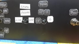
A point to mention about S4 switch (controls the operation of the LLL indicator) on the Front Panel pcb.
In Elektor June 2012, page 24, it shows us the S4 switch in Fig. 7.
As you can see it has 6 switchable positions.
In the text we can read: -
"In the first position the LLL is fed from after the input select and balanced input stage and can be used to check any input"
"In the second position it is fed from the Phono stage only, whichever input is selected"
"The third position removes the signal fed to the LLL and so disables it"
Therefore S4 has 3 switchable positions and not 6 as shown in Fig 7. Why confuse matters by including 6 switchable positions?
Luckily, we can then read "only the first three positions of the switch are used (Line - Phono - Off) and the other three are blocked off by a mechanical stop"
S4's correct name should be: -
LLL Input, then indicated with its 3 positions as Line - Phono - Off
Last edited:
One last question guys.
Has everyone been placing the LLL led from the Front Panel so its indication can be seen?
Has everyone been placing the LLL led from the Front Panel so its indication can be seen?
Well done on getting it working!One last question guys.
Has everyone been placing the LLL led from the Front Panel so its indication can be seen?
I've made my pre-amp front panel so that the LLL LED is visible - if you don't have it visible, there is no purpose to having the LLL selector switch coming through the front panel.
I've mounted mine directly above the LLL switch

Well done on getting it working!
I've made my pre-amp front panel so that the LLL LED is visible - if you don't have it visible, there is no purpose to having the LLL selector switch coming through the front panel.
I've mounted mine directly above the LLL switch
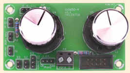
View attachment 680760
Geoff,
Have you been using the phono preamp?
Would love to hear your comments on that.
Nice work by the way.
Great finish Geoffw1!
One other question please.
For the LLL level indicator led, is it correct that the switching of S4 is Line - Phono - Off ?
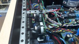
In my opinion the Front Panel pcb is a bad design, and should have been made so that both S4 & S5 can be fitted to the front panel of the case.
As it is, it can't due to the connectors that have to be soldered in place.
One other question please.
For the LLL level indicator led, is it correct that the switching of S4 is Line - Phono - Off ?
In my opinion the Front Panel pcb is a bad design, and should have been made so that both S4 & S5 can be fitted to the front panel of the case.
As it is, it can't due to the connectors that have to be soldered in place.
Last edited:
In my opinion the Front Panel pcb is a bad design, and should have been made so that both S4 & S5 can be fitted to the front panel of the case.
As it is, it can't due to the connectors that have to be soldered in place.
I agree.
Elektor probably did it this way to avoid a 2 layer PCB design. But they shouldn't have done that; a dual layer PCB is not that much more expensive than a single layer PCB.
Attachments
Delange, watch out that Front Panel pcb has the wrong markings on K6, see earlier post #116.
It's such a let down by the Elektor team on the entire build of this Preamplifier.
It's such a let down by the Elektor team on the entire build of this Preamplifier.
Last edited:
Delange - Yes, I've been using the phono stage, with an Ortofon 2M Black MM cartridge, modified Rega RB250 arm, and my Inspire Apollo deck. For MM, it is pretty well silent as far as hum or hiss is concerned. Playing music, it is clean and detailed with a wide sound-stage - very nice! I can't comment on performance with MC as I haven't used it.
Calpe - I can confirm that the switching of S4 is Line - Phono - Off (just as the text in the Elector article says).
As far as mounting the Front panel pcb is concerned, due to its design, I agree that mounting it using the fixing nuts of the Lorlin switches is not possible. I've mounted mine using stand-off pillars fixed to blind tapped holes on the back of the front panel (I have access to a nice pillar drill in the workshop of my neighbour) .
Geoff
Last edited:
Geoff, great fit but will all the connectors fit comfortably?
My front panel is only 3mm thick, so I've got no other choice but to fit the Front Panel further away.
I can't find anywhere black toggle switches for S1, S2 & S3
My front panel is only 3mm thick, so I've got no other choice but to fit the Front Panel further away.
I can't find anywhere black toggle switches for S1, S2 & S3
Last edited:
Geoff, great fit but will all the connectors fit comfortably?
My front panel is only 3mm thick, so I've got no other choice but to fit the Front Panel further away.
I can't find anywhere black toggle switches for S1, S2 & S3
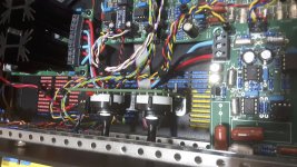
Calpe, you could also use an L-bracket (2 mm thick aluminum) to mount the PCB (see attached picture).
Just a thought.
Attachments
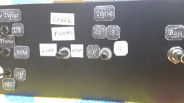
Front Panel
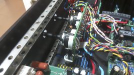
Thanks Delange for your thoughts & idea.
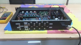
See attached image of what I've done.
Only problem is that there is too much movement of the spindle.
Might have to add an L shape support from the aluminium bar down to the Front Panel so it stops the movement.
Apart from black toggle switches, looking also for some nice black knobs.
Cheers
Thanks Delange for your thoughts & idea.
See attached image of what I've done.
Only problem is that there is too much movement of the spindle.
Might have to add an L shape support from the aluminium bar down to the Front Panel so it stops the movement.
Apart from black toggle switches, looking also for some nice black knobs.
Cheers
Attachments
Last edited:
Why not a bearing bush that can be screwed into the face plate hole? Or, in a pinch, the thread part of an old potentiometer?
Best regards!
Best regards!
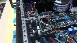
See attached image of what I've done.
Only problem is that there is too much movement of the spindle.
An alu L- plate will indeed stop the movement.
In your current situation, the mechanical pressure will cause the assembly to bend. That won't be the case with an L-plate.
- Status
- Not open for further replies.
- Home
- Source & Line
- Analogue Source
- Doug Self's New Preamp Construction and Pictures