I'm still working on my f6 amplifier. The toroidal transformer primary wire is 18 awg while the secondary is 12 awg. I'm using 16 awg from the rectifiers to the input on the power supply but I don't have enough 16 to complete the output from the power supply to the amplifier boards. I have plenty of 18 awg though. Would 18 awg be acceptable? It's silver plated copper with Teflon insulation. Would doubling the wire be a reasonable solution?
Thanks
Thanks
It's 12gauge for a reason ....
12 gauge is 3.3mm^2 csa (cross sectional area)
18 gauge is 0.82mm^2 csa (cross sectional area)
12 gauge is 3.3mm^2 csa (cross sectional area)
18 gauge is 0.82mm^2 csa (cross sectional area)
If it ddn't click I don't think you'd realised doubling the diameter doesn't double the cross sectional area.
12awg just happens to be twice the thickness (or diameter) of 18awg, but it is not twice the csa
Like Rayma said, get it done right , otherwise it'll just look like a bodge. 😛
12awg just happens to be twice the thickness (or diameter) of 18awg, but it is not twice the csa
Like Rayma said, get it done right , otherwise it'll just look like a bodge. 😛
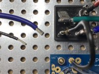
Yes I understand that Mike of course you realize 12 awg will not fit the solder pad on the power supply
Yes I understand that Mike of course you realize 12 awg will not fit the solder pad on the power supply
Pics ?
I’m actually in a similar situation. 16 awg is the biggest gauge that will go into my amplifier boards.
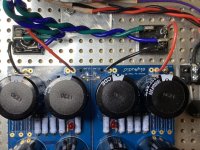
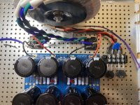
Take a look at the pictures and tell me what you think.
16 awg is the largest wire that will fit the pad and it will handle the current. It's just a bit disconcerting to see the large secondary wires. I assume the # 12 out of the transformer is large enough to accommodate higher current applications.
16 awg is the largest wire that will fit the pad and it will handle the current. It's just a bit disconcerting to see the large secondary wires. I assume the # 12 out of the transformer is large enough to accommodate higher current applications.
Attachments
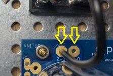
Whats the pitch between the two holes ?
Fit 63951-1 | TE Connectivity, FASTON .250 Uninsulated Spade Connector, 6.35 x 0.81mm Tab Size | RS Components
rightangle or straight
https://www.te.com/usa-en/product-1-726386-2.html
Otherwise I'd be strapping the cable down next to the pad with a tiewrap (you may have to drill an adjacent hole in the uncoppered board for the tiewrap, then solder the wire flat across the two pads
Attachments

Last edited:
Those Faston connectors are excellent; now if you insert wire straight into PCB hole, please do NOT try to enlarge them with a drill, just use largest wire that fits.
If hole is through plated you´ll destroy that but in any case you will end up with a narrower copper ring around it, which will weaken it.
Gluing stuff is considered an inferior Technology in Electronics construction, many don´t consider that PCB tracks and pads are *glued* to PCB base material.
You will not have trouble with using 16Ga wire IF PCB designer only allows that size, he´s "supposed" to be a competent designer , in any case we are using very short lengths, a few inches, inside an amp; unless you grossly exceed ratings and get into plastic melting temperatures, it´s acceptable.
Remember to add track width and thickness to the equation, very little cross section there, just do the Math.
Designs are always a compromise.
You might be able to use a board-mount for a tie-wrap with eyelet so you don't need to drill a hole.
I would also flat-solder 12awg across the contacts.
Wolf
I would also flat-solder 12awg across the contacts.
Wolf
Getting together my materials for the F6 build including power supply. Does anyone have any thoughts on where to get suitable quality wire in the necessary guages and sufficiently assorted colors? Does anybody sell a package for hobbyists like use who don't want to buy large quantities?
Silver-plated, ptfe coated wire in assorted colours and thickness.
Thick for power, thin for signal.
Just don't bother trying to twist it unless you cover the pair with heat-shrink. It's too springy!
https://www.ebay.co.uk/itm/274008227998?var=574024188526 (Other suppliers are available.)
Thick for power, thin for signal.
Just don't bother trying to twist it unless you cover the pair with heat-shrink. It's too springy!
https://www.ebay.co.uk/itm/274008227998?var=574024188526 (Other suppliers are available.)
Short answer, yes. #18 tripled will be ~ #12. If the connector takes only #16, solder the three 18's to a piece of 16 and use it as a patch.
Braid the wires like hair so it looks cool. 🙂

Braid the wires like hair so it looks cool. 🙂
Hello All,
I sometimes like to use twisted pairs taken from Cat 5 or Cat 6 cable for signal hookup wire.
For power or bigger stuff like speaker conductors, SO or SJ cable works well.
https://www.awcwire.com/power-cable-and-portable-cord/service-cord/so
for connection to the PCB try one of these.
https://www.digikey.com/en/products...CBcoLQdIDGUBmBDANgZwKYBoQB7KAbRACYB2SkAXQF9Gg
Thanks DT
what a nice suggestion! I love to recycle. I took apart some CAT5 Belkin cable and they are multi stranded copper, looks like an AWG of 23 or 24.Hello All,
I sometimes like to use twisted pairs taken from Cat 5 or Cat 6 cable for signal hookup wire.
Hello,I used to use UTP from Ethernet cable, but it's such a PITA to strip I switched to RG174.
it is likely the insulation that is difficult to strip is Teflon plenum rated. what makes it difficult to strip keeps it from melting and shrinking back when it is soldered.
Use this tool for stripping.
https://www.amazon.com/Ideal-45-292...ocphy=9032384&hvtargid=pla-561502347818&psc=1
Thanks DT
It was the cheap blue ethernet cable that turns white when you bend it. I couldn't even peel it back with the thread like other cables. My trick was to pull out one pair first, then the others will fall out basically. Still, RG174 is shielded and easier to work with.
- Home
- Design & Build
- Construction Tips
- Doubling wires