I have the project in prelim stages at the moment. On the PE board, keep watch for "Athos" updates...
Later,
Wolf
Later,
Wolf
Guys, do you know of possible DCR principles flaws vs simple BR?
i would imagine the group delay would be worse than a simple BR? I would guess the group delay may be similar to a 4th order BP?
Finally found a pic of the DCRs that fascinated me waaay back in '83, along with the Weems book (which I still have somewhere here in a box) I bought a year earlier.
That woofer though is not the one in the parts & design description, though the enclosure's shape and overall dimensions and driver placement are what was specified in the book, along with the square ports. Except I don't remember Mr. Weems saying to mount the L-pads where you had to get on your knees to adjust them. 🙂 (L-pads can be really useful & used to be present on many commercial and DIY speakers - where did they go?).
I actually like the shape of that cabinet, though I would increase its height a few inches in exchange for a slightly slimmer width & to place the tweeter and mid closer to ear level.
***************************************************
The following is a trip down memory lane so beware! 😎
That RS cloth dome midrange included an incredibly sticky coating, which worried me because of dust issues, since even with a grill cloth, some dust still makes it through to the drivers. So instead I was thinking of using Radio Shack's 4 inch "mighty mouse" woofer that they sold and which was used in their classic Minimus 7 mini-monitor. The tweeter used a 1" mylar dome & along with the very sheer black cloth screen stretched across the dome's opening in the mounting plate (difficult to see in the photo) resulted in a cool "hi-tech" looking driver, at least when I was a teenager! The specified woofer was the 40-1006 (page 63, upper right), a nicely-built woofer that was also used in many of RS' own Realistic speaker systems over the years.
That woofer though is not the one in the parts & design description, though the enclosure's shape and overall dimensions and driver placement are what was specified in the book, along with the square ports. Except I don't remember Mr. Weems saying to mount the L-pads where you had to get on your knees to adjust them. 🙂 (L-pads can be really useful & used to be present on many commercial and DIY speakers - where did they go?).
I actually like the shape of that cabinet, though I would increase its height a few inches in exchange for a slightly slimmer width & to place the tweeter and mid closer to ear level.
***************************************************
The following is a trip down memory lane
so beware! 😎That RS cloth dome midrange included an incredibly sticky coating, which worried me because of dust issues, since even with a grill cloth, some dust still makes it through to the drivers. So instead I was thinking of using Radio Shack's 4 inch "mighty mouse" woofer that they sold and which was used in their classic Minimus 7 mini-monitor. The tweeter used a 1" mylar dome & along with the very sheer black cloth screen stretched across the dome's opening in the mounting plate (difficult to see in the photo) resulted in a cool "hi-tech" looking driver, at least when I was a teenager! The specified woofer was the 40-1006 (page 63, upper right), a nicely-built woofer that was also used in many of RS' own Realistic speaker systems over the years.
hi river , I'm also now considering to use DCR principle in my next built .
I guess you have looked at Claudio Negro's Homepage , which mentions Auspurger's and Weem's in his DCR project-build ,and supports the design with
studies and measures .
L-pads ...why 😕🙄 as intended to fine tune the response of the tweeter and midrange ( I have a box full of them 🙄 ok ,about 6 😱 )
For a serious project I would avoid them ,a resistor is more than enough.
Cool!hi river , I'm also now considering to use DCR principle in my next built .
Yep. A very informative, helpful and well-designed site.I guess you have looked at Claudio Negro's Homepage , which mentions Auspurger's and Weem's in his DCR project-build ,and supports the design with
studies and measures .
I like L-pads because as you alluded to, they allow the user to tailor a tweeter's and midrange's output to the specific room they are located in. A speaker system located in a room with wall-to-wall carpeting & drapes over the windows will react much differently than a room with tile floors & a small throw rug with large windows all around.L-pads ...why 😕🙄 as intended to fine tune the response of the tweeter and midrange ( I have a box full of them 🙄 ok ,about 6 😱 )
For a serious project I would avoid them ,a resistor is more than enough.
L-pads are made of moving parts and contacts cannot be very stable.But that can be forgiven .I seldom found them mounted as a real L-pad ,but only as a trimming resistor in series . If they are really useful ...why not...but 🙄
DCR design is occupying my head lately : it will be a 3 way ,so I'm following classic design WMT being very tall and large but not deep (about double the woofer depth ),so the center of the separating panel would be partially occupied by the midrange chamber ,not allowing to put the port in there . I'm thinking of doubling the ports .Also ,I don't like front firing ducts ...I fear the project would become as usual a paste of various acoustic loads ...a DR-onken?
😱
Hi All... I have a particular situation I would like to get some advice on...
I have built a DCR set in the past starting from the T-S equations and of course, I knew the parameters of the drivers.
This time, I have the cabinets and the drivers, but not the driver parameters.
Cabinet Volume = 9.1 cu ft interior
Drivers = CTS 12" high compliance (also have a pr of 12" Wharfedale's) both with large mags and coils and soft surrounds (not PA-type drivers).
I came across the cabinets for free, quite nice actually, so this is where it all starts for me.
I plan in subdividing to 6 cu ft and 3 cu ft. My question is this:
What port size should I start with, and what tuning method should I use?
I have a SPL meter and woodworking equipment, so I am just looking for a starting point based on the cabinet volume and the params for a "typical" hi-fi 12" driver.
I plan on experimenting with a smaller port length and adding extensions to each until I get it the way I want.
What do you all suggest for the starting port volume, dimensions, etc?
Thanks,
Bill
Find the original tuning frequency, then tune a little lower with the DCR box. You will need probably twice the port area as used in the original box.
Hi, maybe this can be of interest:
Lautsprecher Gehäuseberechnung mit Thiele Small Parameter
Cheers
J
Lautsprecher Gehäuseberechnung mit Thiele Small Parameter
Cheers
J
i would imagine the group delay would be worse than a simple BR? I would guess the group delay may be similar to a 4th order BP?
I didn't know that 4th order BP and bass reflex (also 4th order) had different group delay. If the Qs are the same then 4th order is 4th order. (I'm not saying the Qs have to be the same but we would typically aim for a maximally flat response, making them typically similar. The bandpass rolloff might have an effect, but it would have to be compared to a bass reflex electrical rollof with possibly a higher crossover f.)
I haven't seen a rigorous analysis of a DCR. I do have the old Augspurger paper. Both it and the Negro curves show a 4th order highpass with an extra zero (dip) in the response. Is there any advantage? By that I mean is the efficiency constant higher than BR or can we get the same bass with less excursion? (Real differences, not "pace and timing" differences.)
David S.
I'm not 100% sure but I think Lockwood Audio used to make something very similar.
It was called the Lockwood Major and used 15" Tannoy DualConcentric drivers.
Only ever once seen a picture of the insides. Main cab partition was ported into another partition which was ported to the outside. From what I hear it produced phenomenal deep bass but on the downside it ate woofers for breakfast, lunch and dinner.
On the other hand it predated Thiele&Small so it might be possible to design ones now which would not kill woofers.
I haven't seen a rigorous analysis of a DCR. I do have the old Augspurger paper. Both it and the Negro curves show a 4th order highpass with an extra zero (dip) in the response. Is there any advantage? By that I mean is the efficiency constant higher than BR or can we get the same bass with less excursion? (Real differences, not "pace and timing" differences.)
David S.
It is similar bass with reduced excursion and supposedly therefore distortion.
It is similar bass with reduced excursion and supposedly therefore distortion.
An externally hosted image should be here but it was not working when we last tested it.
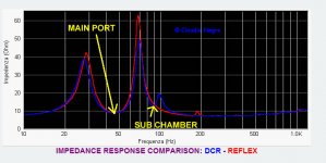
This is Claudio's impedance measurement comparison between BR and DCR; my question isn't directly related to DCR principle and can apply to BR: what do the reduced 28 and 69hz peaks physically mean?
Something to do with the acoustic energy of the global system (driver+vents) at these fr ?
Thanks🙂
An externally hosted image should be here but it was not working when we last tested it.
This is Claudio's impedance measurement comparison between BR and DCR; my question isn't directly related to DCR principle and can apply to BR: what do the reduced 28 and 69hz peaks physically mean?
Something to do with the acoustic energy of the global system (driver+vents) at these fr ?
Thanks🙂
I see both a reduction in peak height and also a slight spread between the two peak frequencies. In a BR box, the single impedance peak of the woofer gets split into two by the box/vent resonant combination. In general, the woofer electrical equivalent is a parallel resonant filter (impedance peak) and the box/vent electrical equivalent is a series resonant filter (impedance dip at 47Hz in this case).
It looks like the components representng the L and C of the cabinet got lower in impedance (smaller L and larger C ) The L represents enclosure compliance and the C vent mass. Don't know why they changed, whether it was how the two cases were set up or, more likely, a coupling of the elements from the second chamber.
Hope that explains a little.
David S.
Guys thanks for your inputs but my question still remain unanswered: physically, what do reduced peaks both sides of Fb mean?
For example, when using a high value series coil with a woofer, we can build a RLC // network to kill the second Z peak as to allow the coil to do his job accurately, OK?: but this tweak doesn't rely to a mechanical process from the driver, i.e. the driver don't change its physical working OK?
So when a same driver is used in two different loads like i.e. two BR, what do peaks of higher or lower value mean?
Thanks
Guys thanks for your inputs but my question still remain unanswered: physically, what do reduced peaks both sides of Fb mean?
So when a same driver is used in two different loads like i.e. two BR, what do peaks of higher or lower value mean?
Thanks
A motional impedance peak is an indication of "ease of drive" at resonance. The driver is both a motor and a generator. At resonance the generator part is creating current in opposition to the drive (motor) part. At that frequency the reactive part of mass and the other reactive part of stiffness cancel each other out. Efficiency climbs to its maximum as only minor losses remain. Since efficiency is high at that frequency, the current generated in opposition to drive is nearly 100% the same value (but opposite in direction). Very little net current flows and we see that as a very high impedance curve.
Any changes to woofer, cabinet size, damping or even cabinet "order" will move the impedance peaks around.
You are correct that adding network components to conjugate out the impedance peaks is a totally different thing and hasn't fundamentally changed the woofer system.
In the end you have to get back to the equivalent circuit and then the impedance curve is simply a view of it from the input terminals. The equivalent circuit comes from the physical parameters. Change the parameters and you will change the impedance curve. In our case the effective compliance of the box and mass of tuning are changed for the primary cavity by the presence of the secondary cavity. That spreads and slightly lowers the first two peaks.
David S.
- Home
- Loudspeakers
- Multi-Way
- Double chamber reflex - why is it not used more often?