Sorry, but I couldn't reproduce the previous state againWhat I was asking was not about the TPs but what did you do to the PCB just before the sound disappeared?
I don't have an oscilloscope, I use the usual methodyou have a 'scope? If not you can check in a general sense wh
Pin1 BCK - 0V
Pin2 WS LRCK - 1,241v
Pin3 Data - 1,254v
And I2S 4PIN
LRCK 1,652v
DATA - 1,65v
BCK - 3,283v
The fact that BCK is showing 0V tells you there's a problem right there. And your I2S input shows BCK = 3.3V which tells me there's a problem even before the I2S reaches the DAC. So check your Amanero.
LRCK and Data look fine.
LRCK and Data look fine.
Thank you for your time and help to solve the problems.
Perhaps yes, there is a problem with Amanero.
I connected with the same I2S 4PIN wire to another device - reclocker Allo KALI. I2S 4PIN input shows BCK = 1.62V. Is it good?
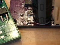
But I found a problem with Pin1 BCK - 0V. The problem is in I2S 4PIN.
See the picture P1.
All pins should be the same as on P2, and BCK is set as on P3. Bad contact P3 and BCK = 0V
I replaced the bad pin and BCK and bad, distorted sound appeared.
But it's very late, it's almost morning here, 4:50, I'll continue today. Goodbye
P1

P2

P3

Perhaps yes, there is a problem with Amanero.
I connected with the same I2S 4PIN wire to another device - reclocker Allo KALI. I2S 4PIN input shows BCK = 1.62V. Is it good?
But I found a problem with Pin1 BCK - 0V. The problem is in I2S 4PIN.
See the picture P1.
All pins should be the same as on P2, and BCK is set as on P3. Bad contact P3 and BCK = 0V
I replaced the bad pin and BCK and bad, distorted sound appeared.
But it's very late, it's almost morning here, 4:50, I'll continue today. Goodbye
P1
P2
P3
I connected with the same I2S 4PIN wire to another device - reclocker Allo KALI. I2S 4PIN input shows BCK = 1.62V. Is it good?
Yes. Hope you sleep well!

New day, I hope today we will solve the problem with the still bad sound )
I repeated all measurements at the control points.
TP1 4.825 V
TP2 2.485 V
TP3 1.659 V
TP8 4.988 V
TP6 5.5368 V (6 V 0.1 V)
TP9 6.530 V (7 V 0.2 V)
TP10 5.360 V (6 V 0.1 V)
TP12 6.510 V (7 V 0.2 V)
TP4 4.230 V (4.8 V 0.2 V)
TP7 4.220 V (4.8 V 0.2 V)
Probably the voltage needs to be adjusted more precisely to the recommended one?
I2S signals go from the input to the TDA1387 chips and further, voltage 1.6v
Shorting PIN7 to ground interrupts the sound, the DAC chips are OK.
What else can be done?
I would not worry about all the voltages being slightly adrift from the target voltages until we solve the problem of the noise/distortion.
Pin7 to GND interrupts the sound? I can't follow this - it should just reduce the sound's volume slightly as one DAC chip is no longer contributing to it. But five others are. So distortion/noise remains no matter which pin7 is shorted?
As to what else can be done - I think check the voltages on pin6 and pin8 of the TDA1387s. They are all paralleled so only two voltages need to be recorded. From memory I think it should be about 1V for those.
You are absolutely right - when shorting contact 7, the sound is muffled, but not interrupted - the voltage on TP4 and TP7 is up to 3.6V. Apparently, I shorted contact 8, it behaves like that, interrupts the sound.
But! When shorting contact 7 of TDA1387 U8, the sound is muffled and becomes much cleaner. It looks like U8 is faulty!
But! When shorting contact 7 of TDA1387 U8, the sound is muffled and becomes much cleaner. It looks like U8 is faulty!
Yes shorting pin8 to GND will definitely give no sound on that channel (the right one). Desolder U8 completely and check there's no noise/distortion. The DAC will work with only 5 chips it just won't play as loud.
Bravo @abraxalito!
With your help, despite all the obstacles, we were able to launch another DORATY. The DAC plays just great. I really liked it, it's not for nothing that they say - the first impression is the most correct.
A huge thank you for developing such a wonderful device.
With your help, despite all the obstacles, we were able to launch another DORATY. The DAC plays just great. I really liked it, it's not for nothing that they say - the first impression is the most correct.
A huge thank you for developing such a wonderful device.
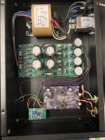
Hi there, I have been enjoying my Dorati for the last year or so, but when I turned it on the other day, it sounded like the speakers were blown (their not) and a little investigating revealed that the LED on the Dorati board was not lit. I can confirm that 12vdc is still supplied to the board but I have not tested anything else.
Richard, let me know where I should start trouble shooting.
Thanks,
Richard, let me know where I should start trouble shooting.
Thanks,
Attachments
The first voltage to check (put black probe on GND or TP0) is TP1 (4.7V) and then, secondly across R1 (51R) with probes on either side of this resistor.
Ok that suggests that Q1 and/or Q2 have likely failed. Best replace both, they are BC856 - BC807 will also work well as a substitute.
Very good, I still have a little baggy marked BC856B that came with the original kit... and it has two extras left!
Here another happy Dorati is born. Freshly built but I was immediately convinced with the sound. Running it straight into headphones and it is clear, full of detail and body, the bass is incredibly defined and very physical. The fact that there are no opamps is lovely and it is truly pleasant to listen. I monitored some soundtracks and got carried away, wanted to keep on listening for hours if I wasn't surrounded by prototype cables because it was so revealing. Didn't do much measurements but the output is like 6Vpp at 20mA. It was more than enough for my HPs (63ohm 106dB/mW).
Everything on the design seems is just genius. The mosfet to increase the DACs voltage, the filter before IV to smoothen wave steps, the class A output stage.
Assembling was very fun and only encountered a few challenges....
I used no-clean flux and some joints didn't make contact at first. I noticed this with the test points that are very useful and well documented! I guess it is best to use a soldering iron first and then heat all SMD parts with a heat gun to be sure. In my case one of the lose joints was the CJ431 regulator so the 74HC86D got 12V and might got damaged. Fortunately the kit brought a spare one so I changed it just in case.
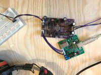
Then I soldered a 1800uF in place of a 1000uF, at the L channel output–they came in the same bag:/. Desoldering broke the output tracks, but I managed to replace the tracks with copper wire (see pic). Fixed 🙂
Last thing it took me a while to realize that I soldered the 0ohm resistors that bypass the output capacitors, so I was getting little to no signal on headphones. But that was it, I removed them and all the glory came in. I still have to experiment with a USB isolator that @abraxalito included in my kit, next a TE7022 USB-I2S converter.
It puzzles me a bit that the output driver is a current source where the power transistor (PXT2907A) is biased with only 10K at the base. The series resistor is 30R and I measured 130hFE for the transistor, so I guess that the base resistor should be 3.9k at least (30*130) to fully saturate the PXT2907A. Or 2.6K if the 30R would be replaced by a 20R for lower impedance headphones. But as said it works perfectly with my mines as it is now.
Oh, and I'm also not so sure if the series 10R at the output is beneficial when driving headphones.
Overall a lovely DAC and it will be very difficult to replace with anything else. It will substitute my current JLH HPamp for daily usage and monitoring.
Everything on the design seems is just genius. The mosfet to increase the DACs voltage, the filter before IV to smoothen wave steps, the class A output stage.
Assembling was very fun and only encountered a few challenges....
I used no-clean flux and some joints didn't make contact at first. I noticed this with the test points that are very useful and well documented! I guess it is best to use a soldering iron first and then heat all SMD parts with a heat gun to be sure. In my case one of the lose joints was the CJ431 regulator so the 74HC86D got 12V and might got damaged. Fortunately the kit brought a spare one so I changed it just in case.
Then I soldered a 1800uF in place of a 1000uF, at the L channel output–they came in the same bag:/. Desoldering broke the output tracks, but I managed to replace the tracks with copper wire (see pic). Fixed 🙂
Last thing it took me a while to realize that I soldered the 0ohm resistors that bypass the output capacitors, so I was getting little to no signal on headphones. But that was it, I removed them and all the glory came in. I still have to experiment with a USB isolator that @abraxalito included in my kit, next a TE7022 USB-I2S converter.
It puzzles me a bit that the output driver is a current source where the power transistor (PXT2907A) is biased with only 10K at the base. The series resistor is 30R and I measured 130hFE for the transistor, so I guess that the base resistor should be 3.9k at least (30*130) to fully saturate the PXT2907A. Or 2.6K if the 30R would be replaced by a 20R for lower impedance headphones. But as said it works perfectly with my mines as it is now.
Oh, and I'm also not so sure if the series 10R at the output is beneficial when driving headphones.
Overall a lovely DAC and it will be very difficult to replace with anything else. It will substitute my current JLH HPamp for daily usage and monitoring.
Attachments
Dorati all the way!
I am still running the Doratis Richard made for me more than 2 years ago. Never felt the need for anything else. Have changed quite a few amps and speakees since then but never the Doratis.
I am still running the Doratis Richard made for me more than 2 years ago. Never felt the need for anything else. Have changed quite a few amps and speakees since then but never the Doratis.
@abraxalito
Question about Doraty circuit. Why pin 7 tda1387 is not used, because according to the reference circuit tda1387 there should be a 1 μF capacitor?
Question about Doraty circuit. Why pin 7 tda1387 is not used, because according to the reference circuit tda1387 there should be a 1 μF capacitor?
- Home
- Vendor's Bazaar
- Dorati NOS DAC kits