Must add: Have done my sims with 6B4G/2A3, 8Vptp, 2,5k:8ohm. Should be in the ballpark of 1W out. 2H and 3H is at ca -48dB. 3H worries me a little.
Yes I mmentioned earier that without the 2a3 load the distortion will be low, but my post shows that even with a 100k load the d3a give -40 dB 2H. Most any high gain high gm tube is simulating poorly as a driver connected to the 2A3.
The 6n6p is showing great result, but too low gain, but the BJT solves that.
The 3A5 is nowhere near that, trying to determine the disconnect. Could you post you asc file?
Member
Joined 2009
Paid Member
Have you guys ever heard of distortion cancellation? Distortion of the driver alone is unimportant. [...] 2A3 isn´t very linear so the driver has to have the same distortion characteristics to conteract.
even with a 100k load the d3a give -40 dB 2H
I'd not want to design around distortion cancellation - I'd be worried that it's a function of too many variables that may change over time. And isn't it mostly a benefit to 2nd harmonic.
Do we worry about the 2nd - isn't it the 3rd and above that we worry over ?

IMHO excessive 2H leads to high IMD, they all do, but an SET should have more 2nd than 3rd, that should be a given but it alwas isnt (at least according the simulaions"
Hey Bigun,
Worry the most about all uneven harmonics. You should also want to get a harmonic spectrum that is gradually falling.
Do we worry about the 2nd - isn't it the 3rd and above that we worry over ?
Worry the most about all uneven harmonics. You should also want to get a harmonic spectrum that is gradually falling.
Last edited:
Hey Bigun,
Worry the most about all uneven harmonics. You should also want to get a harmonic spectrum that is gradually falling.
Gradual falling harmon distortion is import, but if it starts at -15dB There is something worse: non-harmonic disortion.
This BJT scheme from Rod is amazing if you find a tube that matches the current and DC level of the shunt.
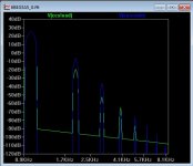
Here is a 6n6p-BJT-6S4S simulation.9Vp into 38 ohm load. Amazing looking FFT. I tried the revintage 3A5 simulation just not having much luck.
But this topology is very promising, because I've always argued that the little high gm high mu triodes aren't very linear with large voltage swings (We417/WE4317,ec). This topology allows us to use low to medium mu tubes that are more linear with no penalty.
Attachments
Member
Joined 2009
Paid Member
Member
Joined 2009
Paid Member
Fun to play with ...
I had a play with this. I took off the output stage so that I would examine the output of the 3A5 and I compared it with and without Cascode.
In Spice at least, the simple CCS load looks better than the Cascode ?
[to use the triode symbol, remove the ".txt" extension from the filename and place it in the same directory as the simulation file]
Attachments
Last edited:
Needs a PCB for proper layout really, but it can be made small & low priced - and the other parts are quite ordinary. I am laying one out now.
Rod,
I am interested in a pair of the PCB when it is ready. I found a place that sell PC86 pretty cheap (1.50 euro each). So, I ordered a bunch of Telefunken PC86. I think they will be perfect for the PCB.
I have a 1st PCB in now, as part of a Panel with other projects.
I plan to try that out, and then see whether it is worth incorporating some shunt regulation, again using ordinary parts.
TFK PC86 should be very fine.
The Russian 6С3П-ЕВ and 6С4П-ЕВ (6S3 & 6S4-EV) are also well-worth a look, with even higher gm.
The high input capacitance of 8 .. 13pF is of little importance with shunt cascode, since there's no Miller effect to augment it.
Tube Tester Files - 6S3PEV - 6C3???
All of these work very well at 150 .. 160V or so. for high voltages, triode-connected pentodes are very useful.
.
I had a play with this. I took off the output stage so that I would examine the output of the 3A5 and I compared it with and without Cascode.
In Spice at least, the simple CCS load looks better than the Cascode ?
[to use the triode symbol, remove the ".txt" extension from the filename and place it in the same directory as the simulation file]
Same results here, I guess I don't consider the shunt 3A5 a good direction, thats a lot of added distortion.
Hey,
Should you use it separate from the output tube? Then the side by side comparision is worth anything.
A 3A5 with transformer, follower or CCS really shines as lineamp. Both sonically and by measurement.
As distortion cancellation works you will get better results with the cascoded 3A5. Don´t forget the 6B4G/2A3 is not linear either. You have to find a driver that complements it to get low distortion at the output and the cascode does. Not that big difference in odd harmonics but not worse.
Bigun, you should correct your 3A5 CCS to just above 8mA. I actually have found they work even better at a little lower Ua=90V and higher Ia=5mA.
I actually have found they work even better at a little lower Ua=90V and higher Ia=5mA.
Per section? That's near the max rating. Curious how they last that way, as they are designed for intermittent transmitter use.
Sheldon
Yes, per section. No signs of losing performance after at least two years of continous (ab)use.
Yes, per section. No signs of losing performance after at least two years of continous (ab)use.
Good to know, thanks. I'm using them in a phono amp at much lower power. Either way, lifetime supply would be cheap.
Sheldon
Since this topic seems to be veering toward hybrid amp (maybe I am wrong), is the circuit similar to this circuit by Mr Ciuffoli ?
Amplifier End by Andrea Ciuffoli
and the push pull in this one ?
DC coupled Hi-end Hybrid Amplifier
Amplifier End by Andrea Ciuffoli
and the push pull in this one ?
DC coupled Hi-end Hybrid Amplifier
no Bubba
way different
Hi, could you explain to this noob (me)
valve for voltage part, sand for current, single stage valve for voltage part ? 😕
This turns the first stage into a current drive and uses the gm with the I/V reistor to get a higher gain out of a medium mu medium gm tube stage. If one would call this a hybrid by ading 1 transistor any tube design these days would be considered a hybrid. The term hybrid seems to be reserved to using a tube for gain and power transistors to replace the OPT. Basically a tube preamp plus an F4 is a classic "hybrid tube amp." Recently there have been more involved designs embeding the tube into an otherwise SS amp.
Back to the topic, the sims with LLTspice show this BJT shunt design to increase disortion driving a 2A3. Are we assuming the spice models just aren't that good? Or is it best to just use a steup transformer on the input in leu of the bjt shunt cascode? (especially with modern Dac's having low output impedance and if we had a preamp we wouldn't need either.)
Back to the topic, the sims with LLTspice show this BJT shunt design to increase disortion driving a 2A3. Are we assuming the spice models just aren't that good? Or is it best to just use a steup transformer on the input in leu of the bjt shunt cascode? (especially with modern Dac's having low output impedance and if we had a preamp we wouldn't need either.)
This turns the first stage into a current drive and uses the gm with the I/V reistor to get a higher gain out of a medium mu medium gm tube stage. If one would call this a hybrid by ading 1 transistor any tube design these days would be considered a hybrid. The term hybrid seems to be reserved to using a tube for gain and power transistors to replace the OPT. Basically a tube preamp plus an F4 is a classic "hybrid tube amp." Recently there have been more involved designs embeding the tube into an otherwise SS amp.
Thanks for the clarification, will Mr Rod be making a balanced kit for this amp, since you have already made a pcb?😀
- Home
- Amplifiers
- Tubes / Valves
- does the 3A5 have the stones to drive a 2A3?