I can't find any details on an Audio Technics SP10, I know of the Technics SP10 and that's not what I am looking for, do you have any pictures?
I have had one good example suggested which is the Micro Seiki DD-20 but if this one fits the bill pictures of the sub chassis and suspension would be useful.
Thanks
I have had one good example suggested which is the Micro Seiki DD-20 but if this one fits the bill pictures of the sub chassis and suspension would be useful.
Thanks
Technically the only difference I can see between the Micro Seiki DD20 and the Denon 1000 is that the former uses the springs in extension while the latter in compression.
I can't find any details on an Audio Technics SP10, I know of the Technics SP10 and that's not what I am looking for, do you have any pictures?
I have had one good example suggested which is the Micro Seiki DD-20 but if this one fits the bill pictures of the sub chassis and suspension would be useful.
Thanks
forgive me for including the word "audio". The SP10 is a suspension DD TT which is what I thought that you were looking for. Best regards Moray James.
TECHNICS SP-10 : SP-10Mk2 : SP-10Mk3 Direct Drive DD Professional Studio Turntables Panasonic
Thanks very much to all for all the help on this one.
The DD-20 is exactly what I was looking for in the form of a suspended turntable so I know it's been done and it works.
All the others suggested are suspension turntables in one way or another but not quite in the form I was looking for.
What I was looking for was someone who had effectively made a direct drive Linn LP12 which is what the DD-20 looks to be.
Mine if it ever does transfer from my head to nuts bolts and springs will be like the DD-20 with a sprung and isolated sub chassis but like a lot of the others will have the springs in compression.
A lot of the examples have actually answered questions I didn't know I had until I started to think through what I really wanted to do and I think I have worked through all the engineering issues in my head now so will start ordering the parts I need and set to work.
Once I have the skeleton chassis built up I will take some pictures and post them up here, the basic mechanics are not going to take long but I have decided to go mad and modify a spare arm to make it 12" to go on this new turntable so that and it's maths will take a little longer I expect.
Again thanks for all the suggestions.
you might want to consider using 0-rings rather than springs you can take a look at how SME do it superb idea as with springs you will always have spring torque and that won't happen with 0-rings. If you do decide to go with spring use four not three that way you can have two clockwise springs and two counter clock wise spring which will help a lot to offset the spring torque. Three spring will always jiggle I had to sell my Oracle Delphi because of that it drove me crazy. Best regards Moray James.
Technically the only difference I can see between the Micro Seiki DD20 and the Denon 1000 is that the former uses the springs in extension while the latter in compression.
+1.
The other difference may be the location of the center of mass of the drive unit/platter vs the suspension. The mass above and below the sub-chassis ought to balance at the plane of the springs. IMO, this is a deficiency in almost every sprung table -- the platter is like a jack-in the box.
Assuming that you fix that issue, the springs must also remain perpendicular to the sub-chassis. Startup torque will eventually bend hanger bolts off vertical. This makes the Denon solution better, since there are no hanger bolts to bend.
Thanks
All very good points which now have me thinking about it a little more.
Because of the limitations of the parts I have to hand and the size and shape of the original motor parts and the metal plate it fits to this has driven down a certain path that will be a bit of trial and error.
The motor unit I have fits in the centre of a circular plate mounted on the plates underside, in the original turntable this then mounted into the original plastic plinth with screws around the circumference.
I intend to use this circular plate as my sub chassis and make an extension to it which will be where the arm mounts. Because of the spindle length I will need to use my suspension in compression as the spindle would not be long enough to suspend it from a top plate.
I intend to use a plate below the motor mount plate/sub chassis which will be the centre of my main chassis, I shall then use my springs/suspension between the centre chassis plate and the sub chassis/motor mount.
I had envisaged using at least 5 suspension points around the circumference of the sub chassis and possibly another somewhere along the arm mount extension 1. because it's pretty heavy and 2. to try and overcome the motor start torque.
I was going to use threaded inserts in the sub chassis/motor mount and then use rubber bushes in the centre plate with sleeved bushes on top of them then the springs in-between the sleeved bushes and the threaded inserts in the sub chassis with screws through the lot from the underside of the centre plate so that the suspension could be adjusted from underneath.
I have sat the motor in it's plate on my chosen springs on the bench and it settles quite nicely so that's where my thoughts are at the moment.
I probably haven’t explained it that well so I will need to put some time together to draw it up.
Maybe the hydraulic dampers of the Braun PS-500 and PS-600 can avoid it.
SME use hydraulic dampers on their suspension towers to keep the motion vertical and very stable. The 0-ring suspension is so simple yet very clever and it makes for easy tuning via inclusion or omission of 0-rings and you don't have to worry about resonant ringing springs either. Using springs is simply designing in problems when you don't have to. Best regards Moray James.
I have a Braun PS-500 and a PS-600, the SME turntables are too much expensives for me.
But I use O-rings very often as springs.
But I use O-rings very often as springs.
Last edited:
I think I would use 4 springs.
I would try and find the centre of gravity ie the single point on which the TT could balance (I suspect that point to be to the back and right of the spindle due to the arm) and move the 4 spring-mounting points out at 90deg to each other until you find a suitable position for them.
That works in my head as long as each spring is the same distance from the centre of gravity.
No idea if that is the correct way of doing it but that is what I would try.
Hi,
The Golmund Studio has a direct drive JVC motor. Motor, platter and arm are mounted on a large sub-chassis, with only 3 springs under it. Really nice TT!
The Golmund Studio has a direct drive JVC motor. Motor, platter and arm are mounted on a large sub-chassis, with only 3 springs under it. Really nice TT!
The Sony PS-2251 is direct drive and suspended. It sounds great. But the suspension is the spring pushing up type and doesn't allow for tuning or adjustment. The suspension is not that effective as the record would skip by the merest bump. I much prefer the hanging spring a la SOTA or O-ring of SME method. Hanging down is better than pushing up!
i like where this is going.
springs.. springs have a rate lets say 10lbft this rate never changes and that is why a spring compresses/extends. its working out how heavy the device is you want to suspend then calculating the spring rates (which i know nothing about. lol)
the more spring you add the more pathways you add for transmission of noise. to counteract the initial start up torque you can either slow start or add a torque spring into the equation. the problem with a torque spring is that it will always want to return to free length so you can actually end up with something worse.
i say three springs in extension with a counter balance weight at the tone-arm and see if you can play with the electronics to give you a soft start.
i've always wanted to try this out and i have an old Technics DD and a Systemdeck IIX kicking about in the attic i might just butcher over the summer 🙂
Well it's built in skeleton form. I got it running last night
I need to play around with the strength of the springs a bit but it basically all works mechanically. The platter spins and doesn't try and turn inside out on start up, it all seems very stable and the suspension goes up and down as it should. I put a record on it let it track which it did well but I can't check the audio yet as there is still work to do on the arm.
I took some pictures but it was a bit dark so I will try some more when I get home from work.
Next jobs are to wire the arm and sort out the counterweight in it, I made a longer arm tube so that it's 12" and that means it needs more weight to allow it to balance. Once I have done that I can see what it sounds like before I look to get the woodworking tools out and make a plinth for it.
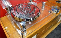
These are some pictures I took the other night which are not great but hopefully you get the idea. It's amazing how a flash shows up all those finger marks, luckily I wont have to clean it all as in the finished article there will be a wooden plinth surrounding and sandwiching the rectangular plate.


Having now wired the tonearm and given it a run amazingly it works.
Much to my wife's (and to be fair my own) surprise it actually produces music!
First impressions are that it sounds very nice indeed, I am going to fit a better cartridge to see where that takes me but I am extremely pleasantly surprised.
The majority of the sweet sound I am sure is down to the arm which started out as an ADC but has had the arm tube replaced with a longer brass item to make it into a 12" arm and been completely rewired with Cardas cable.
Time to get the woodworking tools out and make it look pretty
- Status
- Not open for further replies.
- Home
- Source & Line
- Analogue Source
- Does anyone know of a direct drive turntable with suspension