Mr Ken, For exact thd numbers please look at earlier post DOA - Discrete Op Amps
I'm only now running battery of tests on the grounded grid so for that check back later. I have removed the test cap green Muse and back to DC operation.
In my world, if the thd is below 0.01% then testing becomes more subjective with fft visualization more of interest.
I've used both high performance op-amps and general purpose protected types. The GG is more susceptible to oscillation with high performance parts and I'm still characterizing it. In GG the anode is shielded from cathode by the grounded grid.( No Miller capacitance)
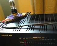
The epiphany listening moments occurred when I repaired an old Zenith Transocean then tuning in by accident to a local AM station playing music. It was I suppose you could say life-changing. Then soon after I built hand wired discrete tube preamp(+-24V) connected to a $3.00 class D TPA3118 amp. More awaking there too. Later I listened to a Sphinx hybrid then was sure on right path. Products_sphinx.htm
I don't like inversion clipping op-amps. Its ugly so I came up with a simple thermal compressor. Yes just purchase newer inversion protected op-amps but a simple limiting compressor allows using legacy op-amps.
I'm only now running battery of tests on the grounded grid so for that check back later. I have removed the test cap green Muse and back to DC operation.
In my world, if the thd is below 0.01% then testing becomes more subjective with fft visualization more of interest.
I've used both high performance op-amps and general purpose protected types. The GG is more susceptible to oscillation with high performance parts and I'm still characterizing it. In GG the anode is shielded from cathode by the grounded grid.( No Miller capacitance)
The epiphany listening moments occurred when I repaired an old Zenith Transocean then tuning in by accident to a local AM station playing music. It was I suppose you could say life-changing. Then soon after I built hand wired discrete tube preamp(+-24V) connected to a $3.00 class D TPA3118 amp. More awaking there too. Later I listened to a Sphinx hybrid then was sure on right path. Products_sphinx.htm
I don't like inversion clipping op-amps. Its ugly so I came up with a simple thermal compressor. Yes just purchase newer inversion protected op-amps but a simple limiting compressor allows using legacy op-amps.

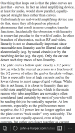
Curious circuit. Because the first stage is a unity gain follower, it's not immediately apparent to me the exact effect that the triode's non-linearity has on the net output. Since the input stage is a follower and so doesn't feature voltage gain, and the total THD is low, the triode may be affecting the bandwidth and/or the distortion spectrum of the op-amp. So, my first thought is that, in conjunction with capacitance at the inverting input, maybe the triode is modulating the op-amp GBW as a function of the signal level? Whatever effects the triode is producing it would interesting to see the distortion spectrum of the output.
It's still unknown how the anode is powered and too if/how the electrons are avoiding the grid.
I reduced the heater to 4.35vdc and no sign of degradation. Below that no emission.
Different tube and different opamp can't be an anomaly.
Bandwidth is good for DC to 50-100khz in unity depending on opamp.
I looked at the opamps schematics no clue.
The first stage output is hi-z but always voltage correct.
Maybe some sort of charge pump effect but it's dc correct.
I'm laying out a general purpose board for easier testing.
Yep as soon as I an get my analyzer back will put up a waterfall.
-
This topology intrigues my curiosity. I may be forced to construct an version for evaluation purposes. 🙂
I do not doubt the net low THD you report. I suppose, that since the triode isn't functioning as a gain setting element, it's non-linear resistance wouldn't appear to induce net output distortion from the first stage. What parameter(s) is the triode effecting on the final output signal? I suspect that the distortion spectrum is being altered, although, since it's low in sum total anyhow, I wonder the subjective significance.
It would be interesting to compare the signal fed to the second stage versus that appearing immediately at the the output (pin-7) of the first stage op-amp. Which would be where the signal corrections for the presence of the triode's non-linearity is apparent.
I think I'm conceptualizing it incorrectly.
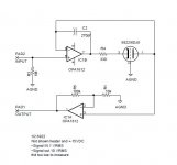
If the anode is held at a constant virtual ground, then modulating the cathode will cause the anode to follow. The overall graph shows anode voltage but for a follower it is aprox the same for a cathode adjusting for bias offset. The opamp takes care of that.
I measured grid current under normal operation and it was below what my meter could measure. During clipping it rises to about 200uA.
The available potential is 30V so looking at the 6DJ8 plot for zero volt grid, it begins to make sense.
The first plot is with grid at signal ground. It is very linear. The 330 ohm resistor helps the opamp remain in SOA.
-
Attachments

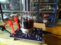
Why not test 6SN7 so here is. Same stellar performance.
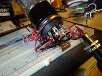
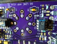
Cleaned up the connections for better layout.
No time now for additional tests. Heading out to the Gulf of Mexico on new ship the VISTA , back in a few weeks.
(pics)
Cleaned up the connections for better layout.
No time now for additional tests. Heading out to the Gulf of Mexico on new ship the VISTA , back in a few weeks.
(pics)
Attachments
Why not test 6SN7 so here is. Same stellar performance.
Yes, I would expect relatively low THD via most triodes. In this follower configuration the triode doesn't determine the op-amp's gain, therefore, the triode's non-linearity does not non-linearly determine the op-amp's gain. However, I suspect the distortion spectrum is being altered, the extent of which is worth determining.
No time now for additional tests. Heading out to the Gulf of Mexico on new ship the VISTA , back in a few weeks.
Have a pleasant journey.
Why not test 6SN7 so here is. Same stellar performance.
Yes, I would expect relatively low THD via most triodes. In this follower configuration the triode doesn't determine the op-amp's gain. However, I suspect the distortion spectrum is being altered, the extent of which is worth determining.
No time now for additional tests. Heading out to the Gulf of Mexico on new ship the VISTA , back in a few weeks.
Have a pleasant journey.
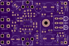
I decided to do a simple pc board to evaluate this circuit before proceeding.
This particular 6SN7 design is beyond the scope of a DIP8 plug-in but it is reducable to very small form factor using the sub-minature triodes.
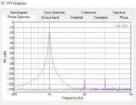
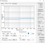
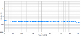
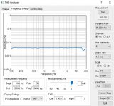
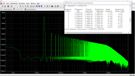
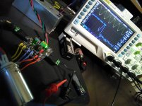
Note on measurements, my test interface has 0.003-4% THD as shown in loopback test. The proto board measures around same so I cannot measure the actual THD using this equipment.
These plots have a TL072 in one socket and OP275 in other. See filenames.
I'm still puzzled as to why the circuit even works. ( some opamps do not work at all)
An old vacuum tube text from 1947 mentions that some electrons will still get to the anode with open plate, even low energy slow electrons. Maybe that is the explanation. Or maybe it the op-amp input bias current, don't know.
plots attached.
Cheers
This particular 6SN7 design is beyond the scope of a DIP8 plug-in but it is reducable to very small form factor using the sub-minature triodes.
Note on measurements, my test interface has 0.003-4% THD as shown in loopback test. The proto board measures around same so I cannot measure the actual THD using this equipment.
These plots have a TL072 in one socket and OP275 in other. See filenames.
I'm still puzzled as to why the circuit even works. ( some opamps do not work at all)
An old vacuum tube text from 1947 mentions that some electrons will still get to the anode with open plate, even low energy slow electrons. Maybe that is the explanation. Or maybe it the op-amp input bias current, don't know.
plots attached.
Cheers
Attachments
-
 OP275-PowerS.JPG40.4 KB · Views: 128
 -
 OP275-THD.JPG79 KB · Views: 111
 -
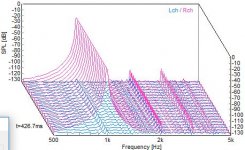 OP275-WFALL.JPG45.9 KB · Views: 108
 -
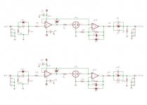 sch.JPG42.7 KB · Views: 157
 -
 TL072-RESP.JPG68.3 KB · Views: 169
 -
 UR22-MkII-loopback-baseline.png6.9 KB · Views: 111
 -
 TL072-THD.JPG77.5 KB · Views: 117
 -
 WP_20190312_12_45_20_Pro (2).jpg729.7 KB · Views: 149
 -
 WP_20190312_12_44_30_Pro.jpg795.6 KB · Views: 175
 -
 WP_20190312_12_47_44_Pro (2).jpg883.5 KB · Views: 144
Thanks, looks intriguing. This pcb is using a medical grade wall wart, working out nicely.
I'm tweaking schematic slightly will put up here once done.
Been auditioning for a week or so using different power amps.
It's a keeper.
I'm tweaking schematic slightly will put up here once done.
Been auditioning for a week or so using different power amps.
It's a keeper.
Attachments
Last edited:
...I'm still puzzled as to why the circuit even works. ( some opamps do not work at all) An old vacuum tube text from 1947 mentions that some electrons will still get to the anode with open plate, even low energy slow electrons. Maybe that is the explanation. Or maybe it the op-amp input bias current, don't know....
I think you are right. There is "NO!" DC current in the plate; also the two opamp inputs need "NO!" DC current. There's always current. nA, pA, fA..zeptoAmps. I would expect some FET-input amps to drive with vacuum leakage, and most BJT-input amps to go off in the weeds.
Is there some reason to take signal down to infinitesimal levels yet squander 2 Watts in a heater?
Yes as expected it was hit/miss on the opamps that did work. The tl072 for example might work until Tc increased bias current. Odd the dc out was correct dc-100khz.
I put the ccs back in (700uA) and so far all opamps work as expected.
Reason for doing that was fA,pA currents alter the tube 3/2 power characteristic.
-see pic-
As previously mentioned a valve in the feedback affects entire product.
Using an opamp plus servo results in low distortion plus 3/2 power profile.
That's why the experiment here.
Attachments
On the subjective side, an issue with music storage and codecs.
I'm guessing as to why but there is definitely a noticeable listening difference from other topologies.
Guessing is the removal of Miller effect or maybe absence of TIM?
Both m4a lossless and mp3/320kbit seem now to sound better without any eq.
Percussion is definitely more pronounced (no eq) and less than perfect program material becomes glaring obvious.
Now I'm thinking may have to use wav files since deficient coding schemes are showing their down sides.
I may have to look at DA too, as the dragonfly 1.0 + 1.2 is easily discerned.
I did notice too the audio quality on W10 seems slack now vs my Fiio.
Next have to move this circuit to DIP8.
-
That is interesting because it matches closely to actual measurement.
One thing that may be artifact is the distortion decreases with increasing amplitude.
I did not mention it earlier because possibly it was my test set-up. Still looking at that.
Thanks for the sim. I did not think it was possible in grounded grid topo.
My measure system bottoms out at .003-4.
Your spectra numbers I've been lookin at, have a hunch on the golden ratios.
Last edited:
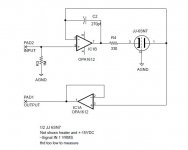
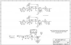
One more rev of the test board to 2.1 and then its locked.
Added CR1,2 (E-701 700uA) and some additional 0.1uF bypass caps.
Changed R1,R9 to 100 ohm for more output PP, changed the comp caps to 100pf fixed.
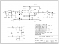
Opamp is specified as SA5532AP and power supply is now shown.
The pdf is good for printing.
Cheers
Added CR1,2 (E-701 700uA) and some additional 0.1uF bypass caps.
Changed R1,R9 to 100 ohm for more output PP, changed the comp caps to 100pf fixed.
Opamp is specified as SA5532AP and power supply is now shown.
The pdf is good for printing.
Cheers
Attachments
The last version of DOA valve hybrid was a failure, I used a 14pin thin quad op amp , the two additional op amps used for buffer since original DOA had hi-z output. The quad package oscillated badly and could not calm it down. I breadboarded same circuit and worked perfectly so chalked up to a bad layout.
Taking baby steps now backed up and did a stand alone board ( not DIP 8 compatible ) with buffers.
Ordered some boards, 2oz copper too for some other reasons. They should be here in week or two.
Two triodes in parallel are supported so reduced high Ra 12AX7 can be used.
Taking baby steps now backed up and did a stand alone board ( not DIP 8 compatible ) with buffers.
Ordered some boards, 2oz copper too for some other reasons. They should be here in week or two.
Two triodes in parallel are supported so reduced high Ra 12AX7 can be used.
Attachments
- Home
- Source & Line
- Analog Line Level
- DOA - Discrete Op Amps