Hi all, thanks for looking.
I'm trying to build a preamp that has an input impedance of about 1Meg, and output impedance of about 1k or less. I know this can be done easily with opamps, but I'm new to op amps and still learning to use them well. (Thanks to all the thoughtful comments and suggestions about op-amps I have received)
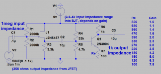
Here is a pre-amp I came up with, it is just a jfet buffer with impedance of 1 Meg (and output impedance of 356ohms) fed into a BJT class A amplifier with gain range of 1-8 (see chart). It has an input impedance of roughly 10k and output impedance of 1k.
The reason I'm wanting a circuit like this is for several reasons. I have various amp units that have gains of 12-32 and input impedances ranging from 10k to 100k. I also have a distortion circuit that has an ouput impedance of 100k. So anyhow, this I believe would allow me link these higher impedance guitars, distortion unit etc, into the lower impedance amps. It would allow me to bump the gain up too.
I will eventually get better with op amps, but when I do get them working right, they sound more sterile and too perfect for me, but that's kind of subjective I suppose.
I'm trying to build a preamp that has an input impedance of about 1Meg, and output impedance of about 1k or less. I know this can be done easily with opamps, but I'm new to op amps and still learning to use them well. (Thanks to all the thoughtful comments and suggestions about op-amps I have received)
Here is a pre-amp I came up with, it is just a jfet buffer with impedance of 1 Meg (and output impedance of 356ohms) fed into a BJT class A amplifier with gain range of 1-8 (see chart). It has an input impedance of roughly 10k and output impedance of 1k.
The reason I'm wanting a circuit like this is for several reasons. I have various amp units that have gains of 12-32 and input impedances ranging from 10k to 100k. I also have a distortion circuit that has an ouput impedance of 100k. So anyhow, this I believe would allow me link these higher impedance guitars, distortion unit etc, into the lower impedance amps. It would allow me to bump the gain up too.
I will eventually get better with op amps, but when I do get them working right, they sound more sterile and too perfect for me, but that's kind of subjective I suppose.
Attachments

Hi all, thanks for looking.
I will eventually get better with op amps, but when I do get them working right, they sound more sterile and too perfect for me, but that's kind of subjective I suppose.
An op amp circuit can have as much colouring as you like.
I use a op amp soft limiter with my guitar and its harmonics vary from minimal to quite rich.
I have used a similar circuit to yours in a record player pre amp and it sounded very good.
[1] 9 volt operation is possible, but has quite a few limits, especially as the batteries inevitably run down. These days, I prefer using 2 little plastic battery-holders, each of which can take 6 batteries of the AA size. That way I can use “enerloop” type rechargeables that don't lose their charge over time. They might only be 1.3 volts, but 12 of them come in at ±9 VDC, with a +9, 0, –9 set of rails.
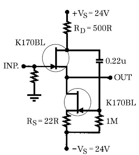
[2] I also like to use the first stage's JFET as the actual amplification stage (with inversion), and the BJT as the 0 dB emitter follower. Its working in a small enough range that it is quite efficient.
[3] And I like using the 2N5460 p-channel JFET “in parallel” with the 5457 to get amplification symmetry for those peaks both positive and negative.
If you are using this for a plucked instrument, I advise keeping the overall gain down. Pickups are remarkably hot these days. It is easy for a pickup to produce 5,000 millivolt peak-to-peak signal.
Anyway, that's about all.
GoatGuy
lowered values of voltage divider resistors
Thank you GoatGuy for the response. I'm kind of new to JFETS having been playing with them for a few days. I kept getting too high of output impedances on the jfet initial stage and I was slightly more experienced working with the bjt (as I've been fooling with them off and on for a month). But I think your idea is better once I get a little more practice with the JFETS.
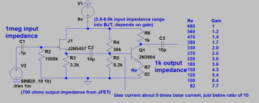
I did notice something about my preamp, the current going down the voltage divider resistors is not greater than 10 x's that going across the base when I do the simulation, so I lowered these resistors and am attaching that jpeg as a correction. I think that's a general rule in design.
Thank you GoatGuy for the response. I'm kind of new to JFETS having been playing with them for a few days. I kept getting too high of output impedances on the jfet initial stage and I was slightly more experienced working with the bjt (as I've been fooling with them off and on for a month). But I think your idea is better once I get a little more practice with the JFETS.
I did notice something about my preamp, the current going down the voltage divider resistors is not greater than 10 x's that going across the base when I do the simulation, so I lowered these resistors and am attaching that jpeg as a correction. I think that's a general rule in design.
Attachments
I don't think you need the biasing resistors at the input/gate of the jFET Buffer.
Does it self bias?
Have a look at Juma's BF820 amplifier.
It is doing what Goatguy is suggesting as an alternative.
And aim for a maximum output of roughly half the battery supply voltage.
i.e. if you assume 5000mVpp as input and apply a maximum gain of +10dB (3times) you have a maximum output of 15Vpp. Use a battery that gets close to +-15Vdc
If you only have ±9Vdc, then think about maximum output levels of 10Vpp (3.5Vac, +13dBu)
Last edited:
eliminated 1 bias resistor on jfet stage
Thanks, I will look up Jumas amplifier. I did remove one biasing resistor and attached the results. It raises the output impedance of the jfet stage a bit, so I had to step up the bias resistors a little at the bjt stage, which leaves the base to bias current ratio to be 9 and I think they say, 10 is minimum typical, but it probably won't matter. It lowers the gain a tad also. I will try the prototype in a week or so, back to work for me.
Thanks, I will look up Jumas amplifier. I did remove one biasing resistor and attached the results. It raises the output impedance of the jfet stage a bit, so I had to step up the bias resistors a little at the bjt stage, which leaves the base to bias current ratio to be 9 and I think they say, 10 is minimum typical, but it probably won't matter. It lowers the gain a tad also. I will try the prototype in a week or so, back to work for me.
Attachments
It works

I just built the above circuit on perfboard (with 85.7ohm Re), but used a 2SK170 JFET as that was all I had. I added a 7812 regulator for the supply and used 10uF electrolytics bypassed with 1uF film caps. The input cap is 0.1uF film. I don't have an O-scope but tested it by using some 60ohm headphones (I know, impedance was way too low) and got sound to come out at low volume. What I heard was clear.
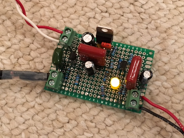
Edit: I tried using it as a pre-amp between my CD player and my Circlophone amp. Sounds very nice - very transparent class A sound. Works well.
This pre-amp confirms that my bag of cheap qnty 40 x 2SK170's from Aliexpress actually work.
This may be just the ticket as a pre-amp for my Pass ACA amp. Same 2SK170 front end, same SE class A operation, simplicity with few parts.
I just built the above circuit on perfboard (with 85.7ohm Re), but used a 2SK170 JFET as that was all I had. I added a 7812 regulator for the supply and used 10uF electrolytics bypassed with 1uF film caps. The input cap is 0.1uF film. I don't have an O-scope but tested it by using some 60ohm headphones (I know, impedance was way too low) and got sound to come out at low volume. What I heard was clear.
Edit: I tried using it as a pre-amp between my CD player and my Circlophone amp. Sounds very nice - very transparent class A sound. Works well.
This pre-amp confirms that my bag of cheap qnty 40 x 2SK170's from Aliexpress actually work.
This may be just the ticket as a pre-amp for my Pass ACA amp. Same 2SK170 front end, same SE class A operation, simplicity with few parts.
Attachments
Last edited:
Measure the Idss of the jFETs.
Then measure the Vp.
You can use those to determine gm. Borbely shows how to measure and calculate.
Then measure the Vp.
You can use those to determine gm. Borbely shows how to measure and calculate.
Measure the Idss of the jFETs.
Then measure the Vp.
You can use those to determine gm. Borbely shows how to measure and calculate.
Do you mean measure the JFETs bare outside of circuit to determine if any good?
Reading up on article by Borbely - looks like changing the input single JFET to follower with constant current source using same JFET allows zero DC offset, so we can skip the AC coupling cap plus reduce HD as shown in Fig 15C in article below.
http://www.linearsystems.com/assets... The New Frontier Part 2, by Erno Bordely.pdf
Fascinating article as it shows that with two SK170's as connected in Fig 16A, you can drive low impedance loads (2.3ohm output impedance) and completely skip the output BJT. If matched devices the THD is very low and will be pure class A as long as output current is less than half quiescent current.
Last edited:
Yes, check your ali jFETs. I can't believe that Ali sells real 2sk170 for cheap prices.
The DC coupled requires a dual polarity supply.
Also read D.Feucht and Pass B1 and DCB1
But I still think you should do what Goatguy suggested.
The DC coupled requires a dual polarity supply.
Also read D.Feucht and Pass B1 and DCB1
But I still think you should do what Goatguy suggested.
Attachments
I see equations for Idss and gm not sure how to measure. Build a breadboard circuit and stick each sk170 and measure voltages to determine Idss? That sounds like work 🙂
I'm not saying they are genuine as we know Toshiba doesn't make them anymore. But they are JFETs and not a blob of inert plastic with 3 metal pins stuck to them 🙂
For 18 cents ea I can't complain.
Thanks for the Feucht article - very helpful.
I'm not saying they are genuine as we know Toshiba doesn't make them anymore. But they are JFETs and not a blob of inert plastic with 3 metal pins stuck to them 🙂
For 18 cents ea I can't complain.
Thanks for the Feucht article - very helpful.
Last edited:
maximum voltage input into pre-amp
Thank you xrk971 for building this. I'm glad it worked for you, I was hoping it would work. I was looking to make something as simple as possible with this. My other idea was to put a 1k trimpot in for Re so that the gain could be adjusted for whatever is needed.
The AMZ basic buffer pages talks about adding the extra resistor to the jfet input buffer and says it will allow for greater input voltages.
"if the input voltage exceeds the gate-source forward voltage plus the bias voltage at the source, the signal will be clipped." http://www.muzique.com/lab/buffers.htm
The question I am wondering about is how high can the input voltage be before it clips?
In ltspice, I simulated and found that there is obvious clipping around 1.4 volts amplitude (2.8v pp). (Voltages just below 1.4 do seem to have the bottom of the sine wave softly attenuated, and this soft attenuation appears to be present down to 1 volt or so, hard to see but easy to measure)
I reverted back to the original biased configuration with two 2 meg resistors at the input. Obvious clipping appears around 4.5v amplitude 9vpp which I guess you'd expect because its a 9 volt power source.
Anyhow, it looks like there is a limit to about 1.3 volts amplitude that you can input to the circuit without clipping, but changing from 1 meg to two 2 meg input resistors allows for alot greater input signals.
And thanks again xr971 for the build!
Garybdmd,
You are welcome. I like simple circuits - they can sound very good and clean when done right. I don't know if a complementary JFET is needed for negative going peaks as the Borbely article uses just N channels and get nice low HD.
The clipping at a relatively low voltage observed, although I was using 12vdc so probably a little higher than 1.4v. I will try the dual 1M resistor to get wider input.
I also want to try the Borbely follower as that just adds another JFET and and a few more resistors. But I think to get a single supply, the output of the follower will still need to be AC coupled.
Here is the circuit I want to try.
Attachments

Last edited:
I am actually looking for a good buffer stage so this may work. It could be combined with a feedback resistor for gain though.
It may be just a source follower, but it can have very high input impedance and very low output impedance, so that's very useful. About modifying if for gain. I look through the articles and it seemed like the gain calculation depends on gm of the transistors. And as far as I can tell that varies from transistor to transistor and must be measured? If that's the case, although its a very nice circuit, each one would have to be custom built. That's not necessarily a problem, but I tend to prefer circuits that don't depend on the peculiarities of any single transistor.
Simple Bass and Treble Controls, 2 caps and 2 pots
Here are 2 easy mods I think.
Bass control:
Between the jfet and bjt stage I think that area is isolated so to speak, so I stuck a bass blocking filter as a bass control. The "resistor" in this high pass filter I think is the 6k load or so on the input to the BJT. the cap "sees" the input to the BJT as 6k resistor and forms a high pass filter. cutoff freq = 1/2pirc. The bass pot just allows the cap to be bypassed or forces the signal through the cap when turned.
Treble control:
This cap sees the 1k output of the BJT stage as its resistor and 1/2piRC the cutoff frequency. The treble control when turned up just removes the cap going to ground as the resistance goes up.
The bass control is isolated from the load, so load shouldn't matter.
The treble control is not isolated from the load, but from loads 10k-1meg, I think it works ok. It doesn't affect the cutoff frequency or curve/shape of the treble control, but I'm thinking the load might effect how fast the treble control works when you turn the pot.
Attachments
Adding some Gain to JFET stage, are these feasible resistor values?
In another post where I was trying to calculate the output and input impedance of a distortion unit, someone pointed out that there is some resistance at the emitter, even when there is no resistance place. This led me to question if the gain chart on the previous schematics were actually correct. Apparently the emitter resistance can be around 400 ohms which makes a maximum gain of about 2 in the previous scheumatics. ltspice simulations don't show this, but I will just need to build and test unless someone has enough experience and leaves some knowledge here. So I thought I'd see if I could place the gain stage at the JFET stage then the emitter BJT emitter follower after the JFET stage. I didn't have much luck getting much Gain out of the JFET stage because to keep the gate reversed biased, I either had to lower the input impedance use extremely high bias resistor. So without practical experience I'm not even sure if this circuit is feasible, specifically if bias resistor of 30meg is way too high. At any rate,
Here is a preamp with gain of about 3 at the jfet stage and about 2 at the BJT stage, with input imped of 1meg, output of 1k. Please comment if these values used in the circuit are within what's typical or normal. (I'm trying to keep to a minimum number of parts, but if I went to 3 transistors, a jfet follower, a bjt amp, and a bjt follower seems to me like it would be a stable easy setup.)
Attachments
- Status
- Not open for further replies.
- Home
- Amplifiers
- Solid State
- Do you think this JFET BJT pre-amp will work ok?