Built this preamp, seems to work ok.
Hi all,
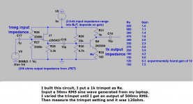
I built the attached preamp and tested it with a sine wave at 50mv RMS and varied the base resistor with a trimpot until I got 500mv RMS out. The 2n3904 I used had an hfe measured on a multimeter of 300. The sine wave was generated from my laptop. I made the ac measurements with a multimeter. I looked at it with an oscilloscope and the waveforms looked ok, but I did not measure with the oscilloscope. I also listened to it simoutaneously and it sounded ok.
So this preamp seems to work ok as best I can tell.
I was thinking going so low with the base resistor was going to throw the gain calculations way off. On a different post as I mentioned earlier I was thinking there was about a 430 ohm resistance coming from the emitter, but after building and testing I think I misinterpreted this other post I read. I'm assuming the 430 ohms must be the resistance across the base to emitter, not, the collector to emitter.
Anyhow, if anyone has any other comments or insights about this circuit, I'd appreciate it. Specifically, why don't I tend to see lower base resistors in class a bjt amps. Is there anything wrong with that? For example, seems like I've seen designs with a 10k collector resistor and 1k emitter resistor (gain ~10 more often than 1k collector and 100 ohm emitter resistor gain ~10) Is there anything wrong with using the lower values? I did this because I was trying to keep the output impedance low enough to go into 10k consumer inputs like aux ins etc if needed.
Hi all,
I built the attached preamp and tested it with a sine wave at 50mv RMS and varied the base resistor with a trimpot until I got 500mv RMS out. The 2n3904 I used had an hfe measured on a multimeter of 300. The sine wave was generated from my laptop. I made the ac measurements with a multimeter. I looked at it with an oscilloscope and the waveforms looked ok, but I did not measure with the oscilloscope. I also listened to it simoutaneously and it sounded ok.
So this preamp seems to work ok as best I can tell.
I was thinking going so low with the base resistor was going to throw the gain calculations way off. On a different post as I mentioned earlier I was thinking there was about a 430 ohm resistance coming from the emitter, but after building and testing I think I misinterpreted this other post I read. I'm assuming the 430 ohms must be the resistance across the base to emitter, not, the collector to emitter.
Anyhow, if anyone has any other comments or insights about this circuit, I'd appreciate it. Specifically, why don't I tend to see lower base resistors in class a bjt amps. Is there anything wrong with that? For example, seems like I've seen designs with a 10k collector resistor and 1k emitter resistor (gain ~10 more often than 1k collector and 100 ohm emitter resistor gain ~10) Is there anything wrong with using the lower values? I did this because I was trying to keep the output impedance low enough to go into 10k consumer inputs like aux ins etc if needed.
Attachments
Nice. What if you moved the output to the emitter pin - could you get 100ohm output impedance? Maybe drive 600ohm headphones?
Ways to get lower impedance output
I just tried that in LTSpice, It basically just acts like an emitter follower with no gain. I do think though you could put some gain in the jfet stage and then do a BJT emitter follower which can have very low output impedance like 8 ohms or so. I've been using this website all the time: BJT - Emitter Follower configuration design calculator to design emitter followers and this one: BJT - Common Emitter configuration design calculator for making the class A amp stuff.
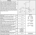
Here's a screen shot of an emitter follower with 20k input impedance and very lower output impedance from the website. I think if you're really looking for low impedance output you're better off going with a jfet amp followed by the BJT emitter follower. I just haven't gotten really comfortable with the JFET amp so much because as I understand you've got to keep the gate voltage lower than the source voltage (reverse bias).
That same website has a jfet calculator also I believe, but you have to look up some datasheet stuff on the transistor.
By the way, if you want to just add a BJT emitter follower this preamp, Even the one I'm attaching here, I believe that would drive headphones just fine, but I have no practical experience, but it seems like it would work ok.
I just tried that in LTSpice, It basically just acts like an emitter follower with no gain. I do think though you could put some gain in the jfet stage and then do a BJT emitter follower which can have very low output impedance like 8 ohms or so. I've been using this website all the time: BJT - Emitter Follower configuration design calculator to design emitter followers and this one: BJT - Common Emitter configuration design calculator for making the class A amp stuff.
Here's a screen shot of an emitter follower with 20k input impedance and very lower output impedance from the website. I think if you're really looking for low impedance output you're better off going with a jfet amp followed by the BJT emitter follower. I just haven't gotten really comfortable with the JFET amp so much because as I understand you've got to keep the gate voltage lower than the source voltage (reverse bias).
That same website has a jfet calculator also I believe, but you have to look up some datasheet stuff on the transistor.
By the way, if you want to just add a BJT emitter follower this preamp, Even the one I'm attaching here, I believe that would drive headphones just fine, but I have no practical experience, but it seems like it would work ok.
Attachments
Used a BJT emitter follower and added Mid control
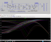
I thought I'd add on the BJT emitter follower to the end of the preamp to lower the output impedance since I had the idea, which by the way, gives room for one more midrange filter, if you want to use it as a preamp with bass mid and treble controls. Anyhow, thought I'd post this with the Bode plot. Not very advanced controls but classic simple controls. (I used a bass control like G and L did on their 2 tone guitar control, but a simple RC high pass filter would work with variable resistance. Likewise I used a treble control which is like a standard treble control on a guitar, but a simple RC low pass filter with variable resistance would work also) Lastly, I used a bridged t filter but inverted the capacitors and resistors from the usual arrangement. I think you can put a fixed resistor and vary the lower resistor for a control also but I haven't tried it. You can also use a bridged t filter with caps and resistors inverted from this arrangement and the left resistor will work as a frequency sweep but there is one more part. I will repost that later
I thought I'd add on the BJT emitter follower to the end of the preamp to lower the output impedance since I had the idea, which by the way, gives room for one more midrange filter, if you want to use it as a preamp with bass mid and treble controls. Anyhow, thought I'd post this with the Bode plot. Not very advanced controls but classic simple controls. (I used a bass control like G and L did on their 2 tone guitar control, but a simple RC high pass filter would work with variable resistance. Likewise I used a treble control which is like a standard treble control on a guitar, but a simple RC low pass filter with variable resistance would work also) Lastly, I used a bridged t filter but inverted the capacitors and resistors from the usual arrangement. I think you can put a fixed resistor and vary the lower resistor for a control also but I haven't tried it. You can also use a bridged t filter with caps and resistors inverted from this arrangement and the left resistor will work as a frequency sweep but there is one more part. I will repost that later
Attachments

Gain measurement may not be very accurate as listed
Hi there, I just realized, when I measured the gain of the circuit a few posts back. I used a digital multimeter and a 1khz signal. As I've come to learn, the simple multimeters do not all measure higher frequency signals very accurately. Since then I have built a meter which measures the peak to peak signal and converts it to a DC signal which can be measured with a multimeter, this is supposed to be more accurate for higher frequencies. Here is a link to that thread. http://www.diyaudio.com/forums/inst...p-how-measure-guage-output-guitar-preamp.html.
I will likely build this circuit and repost a more accurate results of the gains, depending on the emitter resistor values used. I will probably test the bass mid and treble circuit also at that time.
Thanks for looking and helping on this circuit.
You can avoid this error by using a comparison technique.
Attach an accurate stepped attenuator between the Source signal and the input to the amplifier to be measured.
Adjust the stepped attenuator until the source signal voltage equals the amplifier output voltage. Use an AC voltmeter to compare that input voltage vs output voltage.
Since the input and output voltages are equal and since the input and output frequencies are equal, your cheap DMM gives a fairly accurate "comparison" measurement.
The attenuation dialled into the stepped attenuator is equal to the gain of the amplifier.
I have used this technique to measure the gain of power amplifiers from 1Hz to 50kHz. For frequencies below 40Hz I use my rms reading voltmeter. The dual slope measuring DMM readings vary too much at low frequency AC signals.
One small caution: the input impedance of the DMM on Vac should be much higher than the output impedance of both the source and the amplifier. 100times higher is a reasonable minimum to aim for. Many DMM will be at least 1000times higher.
Last edited:
- Status
- Not open for further replies.
- Home
- Amplifiers
- Solid State
- Do you think this JFET BJT pre-amp will work ok?