There is a long running and popular thread on Distributed Mode Loudspeakers started by @xrk971 which you can find here https://www.diyaudio.com/community/threads/a-study-of-dmls-as-a-full-range-speaker.272576/
I have learnt a lot from all the contributors to this thread and have built a number of successful DML’s. Its a very interesting technology that gives great results for not a lot of money which is one of the reasons its been popular on this forum.
This thread is best seen as a stub of the DML thread exploring exciter design. There are many exciters available commercially and they are relatively cheap compared to other loudspeaker drivers so why should we bother looking at DIY options? Same as any other AudioDIY project, to see if it is possible to build cost effective alternatives to commercial designs and, especially in this case, to explore new ideas, push the state of the art and, explore options not available to commercial manufacturers.
Commercial exciter design is targeted at the mass market and so engineering costs are constrained by what the market will bare. All commercial products have to absorb a lot of costs that don’t apply to DIY designs. Take away profit margins, distribution costs, marketing expenses, and some of the engineering costs targeting presentation rather than performance and the amount of money dedicated to sound engineering (sorry!) is less than 50% of the purchase price and for some components can be a lot less.
In the next three posts I will outline each of the areas I am looking at and then, as time goes by, post the results of experiments as they happen. All contributions and questions are warmly welcome as always, but if I end up talking to myself that’s cool to, I do that a lot.
Burnt

Option 1- First Steps
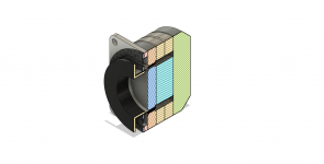
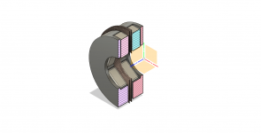
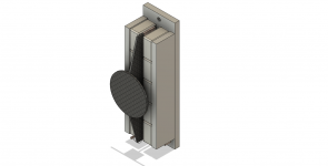
The first step is to try to replicate the design of a typical exciter using off the shelf components and a bit of simple machining. In the CAD model below I am using two ring magnets and a single disc magnet to provide the magnetic flux. Both types are available from stock
The ring magnets are 40mm OD by 25mm ID with a thickness of 5mm
https://www.first4magnets.com/circular-ring-c37/40mm-o-d-x-25mm-i-d-x-5mm-thick-neodymium-magnet-20kg-pull-p3533#ps_0_3639|ps_1_2206
The disc magnet is 20mm DIA with a thickness of 10mm.
https://www.first4magnets.com/circular-disc-rod-c34/20mm-dia-x-10mm-thick-ultra-high-performance-n52-neodymium-magnet-14-6kg-pull-p3605#ps_0_3755|ps_1_3135
Construction
There are three pole pieces, one at the back and the front outer pole ring at the front of the two ring magnets. The second pole piece is positioned at the front on the disc magnet. The pole pieces are iron, low carbon steel is an acceptable alternative.
The inner and outer pole pieces at the front allow me to do two thing, fine tune the voice coil gap to the right clearance and also reduce the area of the gap which increase the flux density. However, iron in the pole gap also introduces a problem in that eddy currents are induced by the coil movement which is a form of distortion. You can reduce the eddy currents by the use of copper which act as a ‘sink’ for the eddy currents.
The voice coil is based on using an aluminium split former and hand wound. I am unlikely to get the sort of tolerances you see in production but I hope to reduce inaccuracy by winding the voice coil first and then adjusting the pole pieces to work with the final dimensions of the voice coil. The machining of the pole pieces is the only part of the assembly that will prove challenging but I have a very good local machine shop that has made turntable bearing for me and they should be more than up to the task.
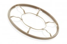
The suspension/ spider is water jet cut from a Carbon-fibre sheet. I will also get some spiders cut from other materials and thicknesses to experiment with.
The pusher plate is also Carbon-fibre to keep the mass down.
Estimated BL Performance
The total magnetic flux available in the circuit is 9496 gauss or 0.95 Tesla
The reduction in pole area in the voice coil increase the flux density to 3.5 times to circa 3.27 Tesla which is a bit meh as a flux in the voice coil gap of 4 Tesla is available in some designs.
Using 30 turns of AWG 28 magnet wire in the voice coil the the wire length is 1.432M
Giving a BL factor of 4.69 which is not too bad.
Compliance
The compliance of the spider/suspension will need to be dialled in by the choice of material and thickness.
Obvious Issues?
As the base design is conventional I don’t think there are any obvious difficulties to be anticipated. Please let me know if you see any blunders I have missed.
So… are there any improvements?
Great question. Not yet but…
As with all Exciter/ Panel combinations, assuming a good exciter performance, the final system performance is dominated by the the panel material properties and the panel size. However, there are some exciter traits that we may be able to experiment with. One typical exciter trait is they tend to have a falling output with increasing frequency. It’s typical to see a falling top end from an exciter. Some remorseless experimenters have found panel materials that have a rising response or ways to add the equivalent of a whizzer cone to combat this problem. Some less adventurous types have just EQ’d out the falling response. But it would be nice not to have the problem in the first place so I am interested to see what can be done with, for example, winding parallel coils so that one may be optimised for the higher frequencies. It might not work but its worth a try.
Power handling is less of a problem than it used to be in the past but I am a firm believer that you can’t have too much power. The problem is coil heating limits power rating so one obvious way to help this is to use ferrofluid in the voice coil gap. Ferro fluid has several benefits and I quote from this article https://www.loudspeakerindustrysour...ofluid-in-the-future-of-the-audio-industry-90
which is is worth a read on the topic
“Ferrofluid has four basic benefits for loudspeakers of all types: 1) thermal transfer; 2) voice coil centering; 3) reduction of power compression; and 4) damping (reduction of signal anomalies). “
Which are nice to have, especially voice coil centering for a hand built assembly.
I’ll report back when I have failed spectacularly or had modest success.
Burnt
The first step is to try to replicate the design of a typical exciter using off the shelf components and a bit of simple machining. In the CAD model below I am using two ring magnets and a single disc magnet to provide the magnetic flux. Both types are available from stock
The ring magnets are 40mm OD by 25mm ID with a thickness of 5mm
https://www.first4magnets.com/circular-ring-c37/40mm-o-d-x-25mm-i-d-x-5mm-thick-neodymium-magnet-20kg-pull-p3533#ps_0_3639|ps_1_2206
The disc magnet is 20mm DIA with a thickness of 10mm.
https://www.first4magnets.com/circular-disc-rod-c34/20mm-dia-x-10mm-thick-ultra-high-performance-n52-neodymium-magnet-14-6kg-pull-p3605#ps_0_3755|ps_1_3135
Construction
There are three pole pieces, one at the back and the front outer pole ring at the front of the two ring magnets. The second pole piece is positioned at the front on the disc magnet. The pole pieces are iron, low carbon steel is an acceptable alternative.
The inner and outer pole pieces at the front allow me to do two thing, fine tune the voice coil gap to the right clearance and also reduce the area of the gap which increase the flux density. However, iron in the pole gap also introduces a problem in that eddy currents are induced by the coil movement which is a form of distortion. You can reduce the eddy currents by the use of copper which act as a ‘sink’ for the eddy currents.
The voice coil is based on using an aluminium split former and hand wound. I am unlikely to get the sort of tolerances you see in production but I hope to reduce inaccuracy by winding the voice coil first and then adjusting the pole pieces to work with the final dimensions of the voice coil. The machining of the pole pieces is the only part of the assembly that will prove challenging but I have a very good local machine shop that has made turntable bearing for me and they should be more than up to the task.
The suspension/ spider is water jet cut from a Carbon-fibre sheet. I will also get some spiders cut from other materials and thicknesses to experiment with.
The pusher plate is also Carbon-fibre to keep the mass down.
Estimated BL Performance
The total magnetic flux available in the circuit is 9496 gauss or 0.95 Tesla
The reduction in pole area in the voice coil increase the flux density to 3.5 times to circa 3.27 Tesla which is a bit meh as a flux in the voice coil gap of 4 Tesla is available in some designs.
Using 30 turns of AWG 28 magnet wire in the voice coil the the wire length is 1.432M
Giving a BL factor of 4.69 which is not too bad.
Compliance
The compliance of the spider/suspension will need to be dialled in by the choice of material and thickness.
Obvious Issues?
As the base design is conventional I don’t think there are any obvious difficulties to be anticipated. Please let me know if you see any blunders I have missed.
So… are there any improvements?
Great question. Not yet but…
As with all Exciter/ Panel combinations, assuming a good exciter performance, the final system performance is dominated by the the panel material properties and the panel size. However, there are some exciter traits that we may be able to experiment with. One typical exciter trait is they tend to have a falling output with increasing frequency. It’s typical to see a falling top end from an exciter. Some remorseless experimenters have found panel materials that have a rising response or ways to add the equivalent of a whizzer cone to combat this problem. Some less adventurous types have just EQ’d out the falling response. But it would be nice not to have the problem in the first place so I am interested to see what can be done with, for example, winding parallel coils so that one may be optimised for the higher frequencies. It might not work but its worth a try.
Power handling is less of a problem than it used to be in the past but I am a firm believer that you can’t have too much power. The problem is coil heating limits power rating so one obvious way to help this is to use ferrofluid in the voice coil gap. Ferro fluid has several benefits and I quote from this article https://www.loudspeakerindustrysour...ofluid-in-the-future-of-the-audio-industry-90
which is is worth a read on the topic
“Ferrofluid has four basic benefits for loudspeakers of all types: 1) thermal transfer; 2) voice coil centering; 3) reduction of power compression; and 4) damping (reduction of signal anomalies). “
Which are nice to have, especially voice coil centering for a hand built assembly.
I’ll report back when I have failed spectacularly or had modest success.
Burnt
Attachments
Option 2- Flat Coils
This option is similar to a short lived design that was marketed at an audio show in the late 70’s or early 80’s. In this design the voice coil was mounted directly onto a stretched PET membrane. The motor assembly was mounted to a spar attached to the perimeter frame. Sonically the design was a success with a lot of positive comments but from what I remember there was no commercial follow through. I think the reason for that was the difficulty in production of aligning the voice coil in the magnet gap consistently.
This design option is a varient on that theme, the key differences being the magnet design and the winding of the voice coil.
Construction
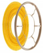
The voice coil for this design is wound spirally and applied directly to the surface of the DML panel. We need a different magnetic field orientation to work with a flat spiral VC and we can achieve that by using ring magnets that have a radial orientation of the poles rather than axial That is, the outer surface of the ring carries one pole and the inner surface carries the opposite pole. What we need are uni-polar versions of this magnet type and they are available if you want to buy hundreds. https://www.alibaba.com/product-detail/Monopole-magnetized-Single-pole-One-pole_1600458563360.html or can fork out $200 a pop. Unfortunately we need two per panel for this design so that $1600 per pair of panels. Ouch! But…you can assemble your own using bar magnets in an iron or steel frame, which may not give as uniform a field as a manufactured magnet but will be good enough for this application. The benefit of this approach is you can dial up a size and shape of field as you wish, e.g. the magnets could be mounted in a race track shaped iron frame.
The motor consists of two coils, one on each side of the panel, and two magnetic assemblies. The magnets are in opposition and their close proximity spreads out the field but also intensifies it between directly opposing magnet faces. To calculate/estimate BL I only use the coil length between the magnet faces. The total immersed length will probably be greater but I will ignore it for now.
In operation the signal to the two coils will need to be reversed or, alternatively, the coils will need to be wound with opposite chirality. Its easier to swap the polarity at the signal inputs so I will do that.
Estimated BL Performance
The magnets used in this assembly are https://www.first4magnets.com/square-c36/20-x-20-x-10mm-thick-n42-neodymium-magnet-14-2kg-pull-p3646#ps_0_3802|ps_1_809
This gives a total flux available of 0.45Tesla per magnet. The published figure are always a maximum at the surface of the magnet and this figure drops away with distance. We need a clearance of circa 3.5 mm which, using an online tool from KG Magnetics https://www.kjmagnetics.com/fieldcalculator.asp approximates to a flux of 0.33 Tesla. But …
We are using two magnets in opposition which will increase the flux density between the pole faces. As I don’t have a means of calculating/approximating that yet I am going to ignore any potential increase for now.
So we have 5 * 2 poles with a flux of 0.33 Tesla each.
A singe coil as shown has a length of 12M but only 55% of that is immersed in the magnetic field. It’s potentially a lot more due to field spread but I can’t calculate that so again i am going to ignore it for now.
The total coil length for this design is 12M, which sounds like a lot but that is because its a spiral coil and we have a lot more room to play with. so 55% of 12M is 6.6 metres per coil or 13.2 meters in total for the motor.
That gives as a BL figure of approximately .33Tesla * 13.2 metres = 4.356 which is in the right ballpark.
Compliance
The compliance is now determined by the DML panel mass and its support and damping, not the motor suspension. This might be fine or it might be a show stopper.
Obvious Issues?
There is one unanswered question. With the coil spread out over an area rather than being concentrated will there be sufficient energy transferred from the coil to the panel? Assuming the applied force is the same the larger contact area means less force per unit area. This may be this designs Achilles heel.
If this is not a problem then the following benefits accrue.
So… are there any improvements here?
There is a significantly reduced moving mass, the coil is applied directly and there is no former or suspension mass to add to the coil mass.
The lateral positioning is not as critical as a conventional voice coil. This may be of interest for PA applications.
There is significantly improved cooling for the coil and therefor higher power handling may be possible.
As with the first design option, each coil can be wound in sections to allow the frequency response to be tailored by varying the impedance independently.
The downside is this is going to be an expensive driver. I am looking at circa £70 for the magnets and another £80 for the machining.
And it might be inefficient.
There is only way to find out…
This option is similar to a short lived design that was marketed at an audio show in the late 70’s or early 80’s. In this design the voice coil was mounted directly onto a stretched PET membrane. The motor assembly was mounted to a spar attached to the perimeter frame. Sonically the design was a success with a lot of positive comments but from what I remember there was no commercial follow through. I think the reason for that was the difficulty in production of aligning the voice coil in the magnet gap consistently.
This design option is a varient on that theme, the key differences being the magnet design and the winding of the voice coil.
Construction
The voice coil for this design is wound spirally and applied directly to the surface of the DML panel. We need a different magnetic field orientation to work with a flat spiral VC and we can achieve that by using ring magnets that have a radial orientation of the poles rather than axial That is, the outer surface of the ring carries one pole and the inner surface carries the opposite pole. What we need are uni-polar versions of this magnet type and they are available if you want to buy hundreds. https://www.alibaba.com/product-detail/Monopole-magnetized-Single-pole-One-pole_1600458563360.html or can fork out $200 a pop. Unfortunately we need two per panel for this design so that $1600 per pair of panels. Ouch! But…you can assemble your own using bar magnets in an iron or steel frame, which may not give as uniform a field as a manufactured magnet but will be good enough for this application. The benefit of this approach is you can dial up a size and shape of field as you wish, e.g. the magnets could be mounted in a race track shaped iron frame.
The motor consists of two coils, one on each side of the panel, and two magnetic assemblies. The magnets are in opposition and their close proximity spreads out the field but also intensifies it between directly opposing magnet faces. To calculate/estimate BL I only use the coil length between the magnet faces. The total immersed length will probably be greater but I will ignore it for now.
In operation the signal to the two coils will need to be reversed or, alternatively, the coils will need to be wound with opposite chirality. Its easier to swap the polarity at the signal inputs so I will do that.
Estimated BL Performance
The magnets used in this assembly are https://www.first4magnets.com/square-c36/20-x-20-x-10mm-thick-n42-neodymium-magnet-14-2kg-pull-p3646#ps_0_3802|ps_1_809
This gives a total flux available of 0.45Tesla per magnet. The published figure are always a maximum at the surface of the magnet and this figure drops away with distance. We need a clearance of circa 3.5 mm which, using an online tool from KG Magnetics https://www.kjmagnetics.com/fieldcalculator.asp approximates to a flux of 0.33 Tesla. But …
We are using two magnets in opposition which will increase the flux density between the pole faces. As I don’t have a means of calculating/approximating that yet I am going to ignore any potential increase for now.
So we have 5 * 2 poles with a flux of 0.33 Tesla each.
A singe coil as shown has a length of 12M but only 55% of that is immersed in the magnetic field. It’s potentially a lot more due to field spread but I can’t calculate that so again i am going to ignore it for now.
The total coil length for this design is 12M, which sounds like a lot but that is because its a spiral coil and we have a lot more room to play with. so 55% of 12M is 6.6 metres per coil or 13.2 meters in total for the motor.
That gives as a BL figure of approximately .33Tesla * 13.2 metres = 4.356 which is in the right ballpark.
Compliance
The compliance is now determined by the DML panel mass and its support and damping, not the motor suspension. This might be fine or it might be a show stopper.
Obvious Issues?
There is one unanswered question. With the coil spread out over an area rather than being concentrated will there be sufficient energy transferred from the coil to the panel? Assuming the applied force is the same the larger contact area means less force per unit area. This may be this designs Achilles heel.
If this is not a problem then the following benefits accrue.
So… are there any improvements here?
There is a significantly reduced moving mass, the coil is applied directly and there is no former or suspension mass to add to the coil mass.
The lateral positioning is not as critical as a conventional voice coil. This may be of interest for PA applications.
There is significantly improved cooling for the coil and therefor higher power handling may be possible.
As with the first design option, each coil can be wound in sections to allow the frequency response to be tailored by varying the impedance independently.
The downside is this is going to be an expensive driver. I am looking at circa £70 for the magnets and another £80 for the machining.
And it might be inefficient.
There is only way to find out…
Attachments
Option 3- Linear Exciter.
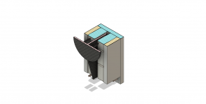
The third option will be familiar to anyone who has studied a Linaeum style driver in that it uses a linear rather than a cylindrical coil. Unlike a Linaeum driver in this case the contact point with the panel remains a small contact patch which can be any shape but in this version is a circular plate. The magnet system is very simple, a line of magnets either side of the voice coil just like a ribbon magnet array.
This design allows great freedom over the scale of the motor compared to the conventional circular format which can be expanded along the long axis of the array and also allows double stacking of magnets to increase the flux in the gap. In the version shown the magnet array o each side is a 5 by 1 array but many variations are possible. 4 by 1, 3 by 1, 4 by 2 , 5 by 2 etc
Construction
In this design the voice coil is a single layer wound on a Carbon Fibre blade. The blade is epoxied to the contact plat with a small Carbon Fibre tube stabilising the join
The magnet structure will be attached to a spar attached to the DMP perimeter frame. The assembly of the motor is not as difficult as if might seem as the position of the voice coil in the magnet gap can be set by removable shims. Using this method the mounting of the contact plate to the panel and the magnet array to the motor spar requires the same degree of care as mounting a conventional exciter. Once fitted, the voice coil gap shims stabilising the voice coils can be removed.
Estimated BL Performance
I am using the same magnets for this design as noted in Option 2 but the voice coil gap can be less than that of Option 2 and is not in oppositions and therefore does not spread and so therefore a higher gap flux of 0.78 Tesla is potentially achievable.
The total coil length is 8M giving a BL factor of 0.78 Tesla * 8M = 6.24 which is a bit higher than average for an exciter.
Compliance
The compliance is now determined by the DML panel mass and its support and damping, not the motor. This might be fine or it might be a show stopper.
Obvious Issues?
There is one issue that may effect this design. As the voice coil heats up the copper in the coil expands. This is accommodated on a cylindrical former by a slit cut in the cylinder body to allow the cylinder to expand. For the 100mm each coil length an increase in temperature fro an ambient temp of 20C to 120c will see the wire grow 0.166mm in length, which is small. It may be required to adopt an alternative method with this design if this degree of change creates any warping of the Carbon Fibre blade but that looks unlikely from the numbers.
There is no restoring force provided by a suspension or, as in the case of Option 2, a restoring EMF from the second motor. This may be a show stopper.
So… are there any improvements here?
There can be a substantial increase in BL with this design should we wish too.
VC cooling is improved over a conventional coil improving power handling.
Its a lot easier to get a small VC gap than Option 2, comparable to a conventional geometry
A motor can be built using stock magnets and extrusions. and the CF armature can be easily hand assembled.
Attachments
Last edited:
Will follow along here. Whats your plan for the spider suspension on the more traditional design? Also what gap width are you giving yourself?]
- Paul
- Paul
Hi Paul,
Welcome! The suspension will be cut from sheet material, CF and spring steel first of all to trial. This might sound a bit odd as a method but typically suspensions on exciters are stiff. I will be trying several different thicknesses to 'dial in' the right compliance.
Gap width will be as tight as I can dare, more experimentation here as well. I am sorry I can't give you a figure but it all depends on how well I can wind the voice coil
Burnt
Won't the Carbon Fibre blade keep on hitting the back plate? Shouldn't there be a vertical groove on the back plate, depth of which more than the excursion? What about a suspension, so it won't even hit the groove in the back plate? Isn't it better to leave a open slit in the back plate, so the Carbon Fibre blade could move through it and back, considering there's a serious suspension?Option 3- Linear Exciter.
The third option will be familiar to anyone who has studied a Linaeum style driver in that it uses a linear rather than a cylindrical coil. Unlike a Linaeum driver in this case the contact point with the panel remains a small contact patch which can be any shape but in this version is a circular plate. The magnet system is very simple, a line of magnets either side of the voice coil just like a ribbon magnet array.
This design allows great freedom over the scale of the motor compared to the conventional circular format which can be expanded along the long axis of the array and also allows double stacking of magnets to increase the flux in the gap. In the version shown the magnet array o each side is a 5 by 1 array but many variations are possible. 4 by 1, 3 by 1, 4 by 2 , 5 by 2 etc
Construction
In this design the voice coil is a single layer wound on a Carbon Fibre blade. The blade is epoxied to the contact plat with a small Carbon Fibre tube stabilising the join
The magnet structure will be attached to a spar attached to the DMP perimeter frame. The assembly of the motor is not as difficult as if might seem as the position of the voice coil in the magnet gap can be set by removable shims. Using this method the mounting of the contact plate to the panel and the magnet array to the motor spar requires the same degree of care as mounting a conventional exciter. Once fitted, the voice coil gap shims stabilising the voice coils can be removed.
Estimated BL Performance
I am using the same magnets for this design as noted in Option 2 but the voice coil gap can be less than that of Option 2 and is not in oppositions and therefore does not spread and so therefore a higher gap flux of 0.78 Tesla is potentially achievable.
The total coil length is 8M giving a BL factor of 0.78 Tesla * 8M = 6.24 which is a bit higher than average for an exciter.
Compliance
The compliance is now determined by the DML panel mass and its support and damping, not the motor. This might be fine or it might be a show stopper.
Obvious Issues?
There is one issue that may effect this design. As the voice coil heats up the copper in the coil expands. This is accommodated on a cylindrical former by a slit cut in the cylinder body to allow the cylinder to expand. For the 100mm each coil length an increase in temperature fro an ambient temp of 20C to 120c will see the wire grow 0.166mm in length, which is small. It may be required to adopt an alternative method with this design if this degree of change creates any warping of the Carbon Fibre blade but that looks unlikely from the numbers.
There is no restoring force provided by a suspension or, as in the case of Option 2, a restoring EMF from the second motor. This may be a show stopper.
So… are there any improvements here?
There can be a substantial increase in BL with this design should we wish too.
VC cooling is improved over a conventional coil improving power handling.
Its a lot easier to get a small VC gap than Option 2, comparable to a conventional geometry
A motor can be built using stock magnets and extrusions. and the CF armature can be easily hand assembled.
Thank you for the question. Its difficult to see in the image but there is a 3mm gap between the CF blade and the back plate. This will give a +/- movement of 6mm which is ample for an exciter attached to a DML panel. It would need to be greater for a DML panel with a very compliant suspension- e.g. the fabric mounted type. This can be easily achieved by moving the blade position forward. To ensure the VC remains within the gap for a large displacement it may be necessary to make the width of the VC coil less and layer the VC, but we are now moving away from my focus on a 'classic' DML which does not need a large displacementWon't the Carbon Fibre blade keep on hitting the back plate? Shouldn't there be a vertical groove on the back plate, depth of which more than the excursion? What about a suspension, so it won't even hit the groove in the back plate? Isn't it better to leave a open slit in the back plate, so the Carbon Fibre blade could move through it and back, considering there's a serious suspension?
Burnt
Last edited:
The problem of linear motor had been thrashed out here. It becomes interesting more and more along that thread. People had been testing their ideas, practically building the motor(s) and the curved DMLs. An offshoot of those experiments was used on flat panel (or two flat panels) DML as shown here.Thank you for the question. Its difficult to see in the image but there is a 3mm gap between the CF blade and the back plate. This will give a +/- movement of 6mm which is ample for an exciter attached to a DML panel. It would need to be greater for a DML panel with a very compliant suspension- e.g. the fabric mounted type. This can be easily achieved by moving the blade position forward. To ensure the VC remains within the gap for a large displacement it may be necessary to make the width of the VC coil less and layer the VC, but we are now moving away from my focus on a 'classic' DML which does not need a large displacement
Burnt
Please do not post off-topic. This thread is about DIY exciter design. If you want to post about curved DML’s start your own thread. It is an interesting topic and deserves development but cross posting is not helpful.
Thanks
Burnt
I was talking about the linear motor design, that is, the linear exciter as you say. They made it to use on something, which is not important here, only the linear motor assembly. Rest you can drop, look for the linear motor assembly.Please do not post off-topic. This thread is about DIY exciter design. If you want to post about curved DML’s start your own thread. It is an interesting topic and deserves development but cross posting is not helpful.
Thanks
Burnt
I always appreciate your effort to help, however you may benefit from a more careful reading before posting. This was the very first sentence in Option 3I was talking about the linear motor design, that is, the linear exciter as you say. They made it to use on something, which is not important here, only the linear motor assembly. Rest you can drop, look for the linear motor assembly.
“The third option will be familiar to anyone who has studied a Linaeum style driver in that it uses a linear rather than a cylindrical coil.”
I have studied this style of driver extensively.
Burnt
Patents are patents, sometimes nothing is ever made, only just to block others for a while, or to bring out another patent. It would help, most probably, if you'd read what sergiu2009 did trying to make the motor. Between them, Joppe and Sergiu did a lot of work with the help of lot of others. Such community help there! Anyway, it's up to you. Will watch how your ideas grow, though.I always appreciate your effort to help, however you may benefit from a more careful reading before posting. This was the very first sentence in Option 3
“The third option will be familiar to anyone who has studied a Linaeum style driver in that it uses a linear rather than a cylindrical coil.”
I have studied this style of driver extensively.
Burnt
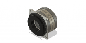
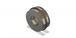
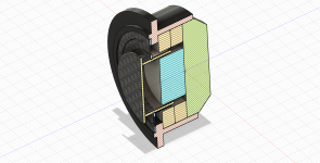
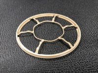
This varient of the Option 1 design abandons the front poles in order to remove the effects of eddy currents on distortion. It uses the same magnets, rear pole piece and suspension as as Option 1. According to the literature on the subject eddy currents can introduce non linearities and are to avoided if possible.
The immediate problem with this design is that the stock magnets force a very large VC gap of 2.5 mm which is not really acceptable. I hope to mitigate this by using a Carbon-fibre former with a 1mm wall section and two coils, one wound on a separate mandrel and then adhered to the inside of the CF former. This will bring the 28AWG coils to 0.5mm of a magnet face. This is still relatively large but I doubt I will be able to do better than this in practice and I will be using ferro-fluid in the gap to help.
What is also not clear is exactly how the magnet field lines will form between the inner and outer poles and I am assuming more fringing than with the iron pole pieces and so have biased the VC position a little forwards to compensate. all had wavy guesses at the moment but I hope to rationalise the design of Option 1 and this design so many of the components are common and its will be easy to assemble both variants.
Burnt.
Attachments
Last edited:
Why block the bobbin completely with that disk?This varient of the Option 1 design abandons the front poles in order to remove the effects of eddy currents on distortion. It uses the same magnets, rear pole piece and suspension as as Option 1. According to the literature on the subject eddy currents can introduce non linearities and are to avoided if possible.
The immediate problem with this design is that the stock magnets force a very large VC gap of 2.5 mm which is not really acceptable. I hope to mitigate this by using a Carbon-fibre former with a 1mm wall section and two coils, one wound on a separate mandrel and then adhered to the inside of the CF former. This will bring the 28AWG coils to 0.5mm of a magnet face. This is still relatively large but I doubt I will be able to do better than this in practice and I will be using ferro-fluid in the gap to help.
What is also not clear is exactly how the magnet field lines will form between the inner and outer poles and I am assuming more fringing than with the iron pole pieces and so have biased the VC position a little forwards to compensate. all had wavy guesses at the moment but I hope to rationalise the design of Option 1 and this design so many of the components are common and its will be easy to assemble both variants.
Burnt.
2.5mm gap is the same as I use in my 20mm motors due to tolerance concerns and making it easier for people to make there own drivers. More will follow soon enough as I push towards it becoming a product.
How are you planning to keep the 20mm N52 central magnet in the ideal position?
Do you feel the magnet strength is required to get your bearings?
Happy to chat to you about my motor design if it interests you but don't want to bloat this thread. I am both Facebook and Twitter. Under the name Polymate3D.
Very much looking forward to see how it goes
- Paul
Hi Paul,2.5mm gap is the same as I use in my 20mm motors due to tolerance concerns and making it easier for people to make there own drivers. More will follow soon enough as I push towards it becoming a product.
How are you planning to keep the 20mm N52 central magnet in the ideal position?
Do you feel the magnet strength is required to get your bearings?
Happy to chat to you about my motor design if it interests you but don't want to bloat this thread. I am both Facebook and Twitter. Under the name Polymate3D.
Very much looking forward to see how it goes
- Paul
That is interesting to know, thank you. I had assumed 2.5mm was too big but if you have made it work that's good to know.
I am going to use jigs to help the assembly. I will assemble the rings to the rear pole first, they really self assemble and the accuracy is usually fine. As you will see from the image I am printing an external housing for this varient and can use that as a jig to guide the ring assembly if required. I will use a thin epoxy film to fix the the ring magnets and the rear pole. When that part of the assembly is cured I will insert a tube ( 3D printed with a 2.4 mm wall) with a sliding fit inside the rings and then insert the central magnet inside the tube. A +/- 0.025 tolerance should be acceptable Once cured I'll pull out the tube. I have some experience assembling high power magnets which helps.
Very happy to chat about motor design, and feel free to critique - I am feeling my way with all this
Burnt
Last edited:
Thanks for your reply. I will cover down below a bit of detail on my mainstream motor. The high end one is a scaled up version of basically the same.
My mainstream motor uses 2x (20x3mm) countersunk N42 neodymium magnets in the centre which use the screw to be under compression. 2 washers in this version are then fitted in between, concentrating the magnetic field before firing out to the outer wall.
The bottom plate and outer wall of the motor are then made up of different washers I can source here in the UK. The outer wall is M24 washers, with the back being 30mm M6 washers. This keeps the iron content fairly similar as the voice coil moves which tends to keep Le around the same which keeps the distortion down.
Wire wise, this one uses 4.8M of 0.18mm wire to create a 3.2 ohm voice coil. I choose this due to being the lowest that works well on cheap USB or class-T style amps. Flux density in this motor is around 0.41T which results in a total Bl of 2.0Tm @ 3.2 Ohm. Inductance peaks at 15 Ohm @ 20Khz which I find to be about as high as I can do and still extend out to 16Khz or so. More winding great for woofers, but not for the extension.
The high end design which is a scaled up version of this moves things up, and larger motors will attempt to push this further. However the one mentioned above has a very consistant Bl across the region it is good for (2.5mm one way). It is also the one I am using on my initial 3D printed transducer seen in the large DML thread.
I will be making magnet motor kits around both these in January for my Fidelity 7 full range driver, and so a lot of time and effort has been put into it to be relatively easy to source (At least here in the UK) and be able to offer with my future product and project as a whole.
Note - Don't use any random magnet supplier. First4Magnets you are looking at are a good candidate.
- Paul
Hi Paul,
I had a look at your site, very impressive print work and I think your product concept is a very interesting one.I think that targeting small Class-T/D amps make a lot of sense, its a huge market. Its much harder developing a conventional driver than an exciter, far more variables, and I had not imagined that you could print the suspension and surrounds- fascinating!
I don't have access to field simulation software and so have to prototype a lot, but I hope to do so in a modular way to allow rapid build and test. I'll be testing the field density using a gauss meter and posting the results I get here so I hope to build a library of data to share with anyone interested.
I agree First4Magnets are very good, I have used them for several years now and find them to be fast and reliable.
Burnt
Burnt, Biomimetic Suspension from B&W can be 3D printed?Hi Paul,
I had a look at your site, very impressive print work and I think your product concept is a very interesting one.I think that targeting small Class-T/D amps make a lot of sense, its a huge market. Its much harder developing a conventional driver than an exciter, far more variables, and I had not imagined that you could print the suspension and surrounds- fascinating!
I don't have access to field simulation software and so have to prototype a lot, but I hope to do so in a modular way to allow rapid build and test. I'll be testing the field density using a gauss meter and posting the results I get here so I hope to build a library of data to share with anyone interested.
I agree First4Magnets are very good, I have used them for several years now and find them to be fast and reliable.
Burnt
It is hinged, very important.
Attachments
- Home
- Loudspeakers
- Full Range
- DML Exciter Design