You can buy very thin aluminum sheets from McMaster Carr Part Number 9060K34. Its .0005 thick 500 sheets for ~$12.50. I bought a box and the sheets are considerably thinner than houshold foil. I've also bought aluminum leaf which is much thinner still http://www.constantines.com. So thin that it's not practical as a true ribbon but I'm thinking of trying it in a magnetic planar on top of very thin mylar (also at McMaster Carr).
No one has spoken about a DIY matching transformer for a true ribbon. Any ideas?
No one has spoken about a DIY matching transformer for a true ribbon. Any ideas?
How about conductive polymer pen traces on Mylar? This is something I have thought about, but never tried, as the pens are expensive...If I had one laying around it would be a different story. Certainly simpler than trying to print, glue or etch a trace on a piece of mylar.
I have seen several ways to get a relatively thin, relatively high resistance (in the range that normal amps can drive) conductors attached to Mylar film. What you suggested could work but you would have to make sure the pen can write on the mylar and the flexing won't break the traces. I've seen a couple of pages where they use various spray adhesives.
This is "cheating" in that you don't end up with a "true" ribbon but instead you get a planar magnetic driver. As I understand it, a true ribbon must have a metal film with no backing. The advantage is that you end up with a lighter vibrating element because you don't have the weight of the backing mylar. The biggest disadvantage is this gives you a very low resistance, usually much less than an ohm. The commercial ribbons you can buy, such as the Ravens, have a built in impedance matching transformer to match the low riboon impedance to a 4-8 ohm impedance an amp can drive. The transformer has to do this while tranferring power to the ribbon and having low distortion and flat frequency response over the range of the ribbon. Depending on the size of the ribbon you build this can start as low as the hundreds of hz and reach out past 20k.
I've seen very little about DIY ribbon transformers. I did see a site or a post that talked about converting a PC switching power supply transformer ferite ring for ribbon use but here was no details.
Has anybody seen anything on the topic of true ribbon driver matching transformers?
On a website about ribbon mics the author said that aluminum leaf is the perfect thing for replacement. It's possible that tweeters need to be tougher than mics.....
I've seen the site and, based on reading it, I bought some aluminum leaf. I can confirm that it is much too delicate to consider using as a driver element on its own. It is very difficult to even touch it without having it stick and tear. I bought it with the intention of trying it as the conductor on mylar.
I made some "proof of concept" ribbons with pleated kitchen foil suspended between two 1.5 x 3/4 x 3/8 magnets and with the ends wrapped around some wire and attached to a small wood bar which kept the magnets apart. They would move a great deal with DC and enough DC would stretch out the pleats but not break the ribbon. Resistance was not measurable and I drove them with a boombox I didn't care about and got a little sound, but this was preinternet (~14+ yrs ago) and I didn't find any workable transformers at a local surplus shop. I made some exponential horns for the fun of it out of tagboard and saw little improvement, and that was the end of my trial. If I had access to a shop and tools, I would have made a better gap to concentrate the field and use thinner foil to hopefully get a better sensitivity, and I would have looked for something to make a transformer out of..
I have thought about several ways of doing planars since then - tape and magnet wire, conductive pens on mylar, and a couple different gap geometries. Someday....
I have thought about several ways of doing planars since then - tape and magnet wire, conductive pens on mylar, and a couple different gap geometries. Someday....
Hi all,
In my earlier post I declared the design challenges to be the magnetic circuit design and the transformer.
We have not gotten very far with even the magnetic circuit design. For example, one person stated that you should have a field strength of 1 to 1.5 Tesla. Another person wrote to wish us luck achieving even a 1 Tesla field with permanent magnets.
So, my question is this "If all other variables are held constant, what is the relative output loss for a lesser field?" How much reduction in acoustic output (in db) could we expect if we have to settle for a 1Tesla field instead of a 1.5 field? What if we have to even go lower? What about a .6 Tesla field instead of a 1.5 Tesla field? I am not talking about absolute values here, just relative values along the variable of field strength.
Does anyone know?
Mark
The cheaper ribbons usually have a sensitivity of 96db if thats any help?
Another thing to consider would be having a lower resistance ribbon than usual (either thicker, wider or multiple ribbons) and make a bulkier transformer to increase current. Current is proportional to the force on the conductor (I think ) so we can increase that to compensate for the reduced magnetic field.
The other variable is wire length. A .5 tesla gap over 20cm would be easier than 1.5 tesla over 6.5cm. Whether the acoustic output is the same I don't know.
Since its purely resistive they'd pretty much fit the F = I * L * B (current, length of wire, field strength) perfectly.
Any other comments?
Another thing to consider would be having a lower resistance ribbon than usual (either thicker, wider or multiple ribbons) and make a bulkier transformer to increase current. Current is proportional to the force on the conductor (I think
) so we can increase that to compensate for the reduced magnetic field.The other variable is wire length. A .5 tesla gap over 20cm would be easier than 1.5 tesla over 6.5cm. Whether the acoustic output is the same I don't know.
Since its purely resistive they'd pretty much fit the F = I * L * B (current, length of wire, field strength) perfectly.
Any other comments?
I am not too worried about getting an "adequate" field strength. Other DIYers have gotten good results using ceramic magnets. Now you can get Neodymiun magnets that are 10 time as powerfull as the best ceramic magnets. The drawback is cost, but if you are making a Raven-sized ribbon with ~ 5 inch long ribbon even the cost is not outrageous. $25 will buy you a lot of strong magnets. The limiting factor is going to be the size of the gap (I.E. the width of the ribbon element) and the saturation of the steel pole pieces and back plate. I don't think the physical and magnetic design will be very complicated.
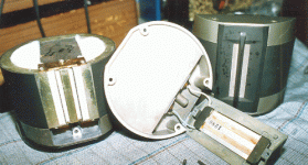
Take a look at the hand drawn "U" shaped design using ceramic magnets here:
http://ldsg.snippets.org/ALSR/rphotos.html
You could replace the ceramic magnets with something like this:
http://www.amazingmagnets.com/products.asp?ID=01445
You would end up with a much stronger field strength and greater sensitivity. Or you could go with smaller neodymium magnets and get the same field strength. Otr lastly you could stick with ceramic magnets but you would have to find a different source. Amazing magnets only sells neodymium.
The key is the transformer as it is not practical to try to drive a ribbon with < .5 ohms with any normal amplifier.
Hi all,
Matt, Thanks for using the word "proportional" and the formula. As I read the formula all terms are proportional to force. From that, then reducing field strength by one-half while holding the other terms constant will reduce force by one-half. Here is where another assumption is needed to answer my question. Is force in this instance also proportional to acoustic power. If it is, then we can plug this into the power ratio to decibel loss tables and we would have a mere reduction of 3 db in output.
Since increasing the field from 1 to 1.5 Tesla is only a 50% increase, then output would only increase by 1.5 db.
If this is correct, then it tells us something very meaningful for what we want to accomplish in terms of magnet circuit design.
So, what do you think, is this the correct relationship between magnetic motor force and acoustic output?
Mark
I'll just interject some food for thought... 🙂
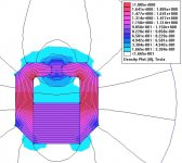
I just did a couple off-the-cuff sims to see what gap fields might be attainable and how return circuit materials related.
In this first sim, the magnet is a monsterous slug of 40 MGOe NdFeB 2 inches wide and 2.3 inches thick . The return circuit is vanadium permendur--the most permeable material in my library.
As you can see, the resulting field across the half-inch gap is right around 1 Tesla at its mid-gap densest. This is why Pjotr described 1T as "damn good." 😀
Also notice that despite the use of permendure, which is not anywhere near saturation at any point in this circuit, stray flux lines are flying off everywhere. This is because the flux doesn't feel especially inspired to stay in even an ideal circuit if it's facing a large gap reluctance.
I just did a couple off-the-cuff sims to see what gap fields might be attainable and how return circuit materials related.
In this first sim, the magnet is a monsterous slug of 40 MGOe NdFeB 2 inches wide and 2.3 inches thick
. The return circuit is vanadium permendur--the most permeable material in my library.As you can see, the resulting field across the half-inch gap is right around 1 Tesla at its mid-gap densest. This is why Pjotr described 1T as "damn good." 😀
Also notice that despite the use of permendure, which is not anywhere near saturation at any point in this circuit, stray flux lines are flying off everywhere. This is because the flux doesn't feel especially inspired to stay in even an ideal circuit if it's facing a large gap reluctance.
Attachments
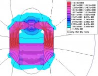
To look at the effect of materials, I left everything the same in this second sim, except the return circuit is now cheap 1020 steel.
As you can see, the gap field is still right around 1T. So, word to the wise: save a few bucks on your return circuit! 🙂
As you can see, the gap field is still right around 1T. So, word to the wise: save a few bucks on your return circuit! 🙂
Attachments
Hi Bill F.,
Thanks for the sim jpegs. Would you be willing to share the .FEMM files?
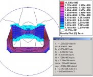
Also, one reason for all the stray flux lines is that you have designed a classic high leakage circuit. This is the most typical design used for ribbon drivers because it is cheapest to build. A low leakage design would have the lines of flux concentrated at the gap.
If the calculations Matt and I have worked out are correct, except for cathode ray tube TV interference, there is no reason to use high permeability materials and no reason to use low leakage magnetic circuits.
Both of these make the challenge of magnetic circuit design less challenging.
Mark
Thanks for the sim jpegs. Would you be willing to share the .FEMM files?
Also, one reason for all the stray flux lines is that you have designed a classic high leakage circuit. This is the most typical design used for ribbon drivers because it is cheapest to build. A low leakage design would have the lines of flux concentrated at the gap.
If the calculations Matt and I have worked out are correct, except for cathode ray tube TV interference, there is no reason to use high permeability materials and no reason to use low leakage magnetic circuits.
Both of these make the challenge of magnetic circuit design less challenging.
Mark
Mark, you have mail. 🙂
Ok, I'm up to challenge. 😉
In my continuing effort to deliver your money's worth, here's a low-leakage design--permendur again, just of giggles. External fields are mostly gone, but there's still internal leakage, and no more flux in the gap... 🙁 How do you propose to better turn leakage into gap flux?
Also, one reason for all the stray flux lines is that you have designed a classic high leakage circuit. This is the most typical design used for ribbon drivers because it is cheapest to build. A low leakage design would have the lines of flux concentrated at the gap.
Ok, I'm up to challenge. 😉
In my continuing effort to deliver your money's worth, here's a low-leakage design--permendur again, just of giggles. External fields are mostly gone, but there's still internal leakage, and no more flux in the gap... 🙁 How do you propose to better turn leakage into gap flux?
Attachments
SIMPLE RIBBON EFFICIENCY EQUATIONS
SIMPLE RIBBON EFFICIENCY EQUATIONS
For a ribbon tweeter, magnetic fields of 0.5 to 1 Tesla are possible at modest cost.
A=ribbon area meter^2
B=magnetic field in Telsa
%= percent of ribbon which conducts current(100=100%)
m= mass of ribbon in grams
Efficiency = A^2 * B^2 * % / m
spl 112.2 + 10*(LOG(wfficiency)/LOG(10))
senS effeciency + LOG(8/resistance)/LOG(10)
Ok , somewhere here I saw a reference to the resistance of a ribbon at about 1/2 ohm. That was more than I expected.
How about this:
Glue the thin ribbon to a piece of plastic that will dissolve in acetone. Now you can cut a labyrinth pattern in it similar to what the flat film tweeters have.
clamp the film between your clamps- they would have to be non-conductive. Then put it in the acetone and dissolve the plastic sheet. Now bolt your clamp frame into the magnet structure.
If the pattern is 8 strips, maybe we could get 4 ohms without a transformer. OR would the current flowing in different directions cause the strips to move in opposite directions? Maybe this is why planar drivers have the magnets front and back....
Can't post the diagram..
Hi all,
My thanks to Bill F. for sending me his reasoning on the SPL to B relationship. He is correct. I have cross checked and verified it and I have had confirmation from an independent source. A doubling or halving of B will produce a 6db change in output (all other variables held constant). So, if you wanted 96 db/1w/1m and could only build a magnetic field with half the desired strength, then you would have 90 db/1w/1m.
Also, my thanks to Linesource for the efficiency equations. I believe this thread now has enough information in it (along with FEMM) so all may design whatever motor structure is near and dear to their heart.
Now the only other obstacle is the transformer design and FEMM can help. Keep in mind that you are not making ribbon subwoofers so design demands are less. You can get away with really simple transformer construction. Just remember to keep the output winding and connections to ribbon very large.
May you all experience the joy of serious design,
Mark
DIRECT DRIVE RIBBON
Mark...
I have a thread on a 25 watt into 1 ohm Class A amp circuit running which looks like it could safely drive 0.5 ohm loads. Instead of a transformer one could just pad up their ribbon with a non-inductive resistor to 0.5 ohms and drive it directly. No transformer phase shifts or saturation issues. Just a loss in efficiency.
- Status
- Not open for further replies.
- Home
- Loudspeakers
- Multi-Way
- DIY'ing ribbon drivers?