Suggest using the same gauge as the rail supplies but double up. (I used stranded 16ga from ApexJr, https://www.ebay.com/str/apexjr?_trksid=p2047675.l2563, for all wiring in my F6s)
The idea is making sure the wiring can handle the total current draw while creating a lower resistance path than anything else in the amp.
Here's a helpful web-site: https://www.powerstream.com/Wire_Size.htm
The idea is making sure the wiring can handle the total current draw while creating a lower resistance path than anything else in the amp.
Here's a helpful web-site: https://www.powerstream.com/Wire_Size.htm
Thank you 6sx7. Thanks also for the rationale. I learn slowly!
I'm looking over my boards and parts today. I notice that each of the two boards has one large resistor spot that's unlabeled (blank). An R1, an R2 or an R3 could conceivably fit. Since one board has R2 and R3 labeled and then a blank, I assume an R1 is intended for the blank (since both circuits should be identical though they're laid out differently, yes?). The other has R1 and R3 labeled and then a blank, so I assume an R2 goes there. Or is this some other kind of basic intelligence test that I'm failing?
Also, want to order my JFETS. I need an NNPP quad it appears. There are two options for that quad on the store site, one that's 6-8mA and one that's 8-11 mA. Not having any idea what the difference is, can you tell me which one of those options I need?
Many thanks,
J
If I'm following, this is for an F6? Not to be dismissive but match the schematic to the boards. Learning the layout will help with troubleshooting should it come to that. https://www.diyaudio.com/community/threads/f6-illustrated-build-guide.277850/Thank you 6sx7. Thanks also for the rationale. I learn slowly!
I'm looking over my boards and parts today. I notice that each of the two boards has one large resistor spot that's unlabeled (blank). An R1, an R2 or an R3 could conceivably fit. Since one board has R2 and R3 labeled and then a blank, I assume an R1 is intended for the blank (since both circuits should be identical though they're laid out differently, yes?). The other has R1 and R3 labeled and then a blank, so I assume an R2 goes there. Or is this some other kind of basic intelligence test that I'm failing?
Also, want to order my JFETS. I need an NNPP quad it appears. There are two options for that quad on the store site, one that's 6-8mA and one that's 8-11 mA. Not having any idea what the difference is, can you tell me which one of those options I need?
Many thanks,
J
As for the matching, I have not made time to research the how and why JFETs are matched. Possibly others could answer in the respective build thread. BTW, I went with 8-11 mA but I chose the Spinal Tap line of reasoning. Seriously.
How can anyone argue with Nigel Tufnel’s line of reasoning? Plus they’re five bucks more, so they have to be good.
But yes I can see where the holes are on the schematic, I’ll just fill in the blanks. Was mostly double checking that there wasn’t a magic part out there that wasn’t on the BOM.
Cheerio and thanks,
J
But yes I can see where the holes are on the schematic, I’ll just fill in the blanks. Was mostly double checking that there wasn’t a magic part out there that wasn’t on the BOM.
Cheerio and thanks,
J
Oh, ya. gotchya now. Yes, no magic part missing. The silkscreening was not complete.How can anyone argue with Nigel Tufnel’s line of reasoning? Plus they’re five bucks more, so they have to be good.
But yes I can see where the holes are on the schematic, I’ll just fill in the blanks. Was mostly double checking that there wasn’t a magic part out there that wasn’t on the BOM.
Cheerio and thanks,
J

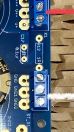
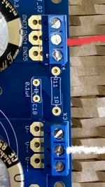
The critical connections to not blow up your caps are from your rectifiers to the filter board. I can't quite see how they're marked on the boards, and I don't have a set in front of me. Your notes for output are correct based on the board markings.
If I recall correctly, each half is identical, and I think you've got it correct. Just to be sure, another pic from top down with the input side of the filter board would be helpful. Someone may just remember the layout and be able to tell you from the existing pic. Either that, or just be sure to hook up + to + and - to - for the input to the filter boards just as they're marked. No reversing on the input.
If I recall correctly, each half is identical, and I think you've got it correct. Just to be sure, another pic from top down with the input side of the filter board would be helpful. Someone may just remember the layout and be able to tell you from the existing pic. Either that, or just be sure to hook up + to + and - to - for the input to the filter boards just as they're marked. No reversing on the input.
Thank you. See attached for detail from my previous picture. Top right and bottom right for inputs.
My logic followed the + and - areas for the big caps on the board, so it made sense to me (but I’m an electrical simpleton). I’ll test with my 2 meanwelll SMPS to see if things power up appropriately.
My logic followed the + and - areas for the big caps on the board, so it made sense to me (but I’m an electrical simpleton). I’ll test with my 2 meanwelll SMPS to see if things power up appropriately.
Attachments

So then. Things are progressing fairly well. I'm working on power supply installation, using an AnTek AS-3218 18V transformer. I plan to wire the terminal block according to the diagram from the Aleph J build blog:
https://www.diyaudio.com/community/...rated-build-guide.244788/page-39#post-5640721
My question however is: how do I know which of the primary windings from the transformer is the "first" and which is the "second"? I've tested my red-black pairs for continuity, so I've got that going for me. However I don't know which pair is "Red 1 and Back 2" and which one is "Red 3 and Black 4".
I presume the same question applies to the leads on the other that connect to the rectifier bridges, but first thing's first.
Also, can't help but notice I don't have an AC power cord for when the time comes (eventually) to power this beast up. Any part suggestions?
Many thanks again from J T. Noob.
J
They are both coupled in the same magnetic field so pick one pair and call it red1/black 2. AC is wonderfully ambiguous at times. Maxwell was smart. Some might say "Get Smart".
Funny enough that actually makes sense. Thanks. Any suggestions on an AC cord? Do they not include them so newbie goofs like me won’t electrocute themselves?
any 16 AWG (or larger) IEC cord used for a PC or similar works fine. Assuming you're in the US, something like this: https://www.newegg.com/black-tripp-lite-6-ft-others/p/N82E16812120756?Description=IEC cable&cm_re=IEC_cable--12-120-756--Product&quicklink=true
Or you could waste money like I did because they look cool: https://www.audioadvisor.com/prodinfo.asp?number=PGAC14S2
Or you could waste money like I did because they look cool: https://www.audioadvisor.com/prodinfo.asp?number=PGAC14S2
More basic questions here. Making the connections from the amp boards to the power supply. The PSU has three connections for V+ marked V++ and V+++. I assume one is as good as another, the same for V- and all the grounds GND through GND 5?
Or am I all backwards on this thing?
Or am I all backwards on this thing?
Yar. V+ is V++ is V+++.
Same for - and GND.
Can verify with a DMM if you want to be absolutely sure.
Same for - and GND.
Can verify with a DMM if you want to be absolutely sure.
No that’s good. I think between you and the tutorials (which say nothing at all on the subject) I’m good. It’ll be testing time shortly anyway. Sometimes I think I’m building this beast only to take it completely apart to see where I went wrong, but that’d be OK too. There’s no rush and I’m interested to learn.
Thanks!
Thanks!
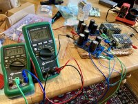
The latest is this: I got through the initial powerup. The problem is that my multimeter is showing a -25.57 volts for both V+ to ground and V- to ground. What have I done wrong here?
J
J
Is your probe orientation correct for each measurement?
what are you measuring from V+ to V-?
what are you measuring from V+ to V-?
They may not be. I'm new at this.Is your probe orientation correct for each measurement?
what are you measuring from V+ to V-?
- Home
- Amplifiers
- Power Supplies
- diyAudio Power Supply Circuit Board v3 illustrated build guide