Do you have your transformer wires running under the rectifier board?
Yes exactly. The PSU sits on top of the transformer, wires are soldered from below.
(Ah, and I followed 6L6‘s build guides very closely 😉 )
Last edited:
Thank you for the help.
And thank you for doing the build guides along with all of the photos. I have managed to have a lot of fun building the stuff from everyone's efforts here. Incredible resource.
And thank you for doing the build guides along with all of the photos. I have managed to have a lot of fun building the stuff from everyone's efforts here. Incredible resource.
Last edited:
I'm planning an M2x with Antec 400VA toroid with 18v/18v secondaries. I have on hand eight Nichicon 35v 10,000uF snap-in caps. Are these OK for this application? Thanks.
To3 Diodes
I'm curious. The universal power supply circuit board has holes for three prong diodes. However in the photo's, it appears that you have clipped-off one of the anodes.
I have purchased To3 diodes for my PSU power supply. They have two anodes and a cathode. Should I clip-off one of the anodes before soldering the diodes to the boards(s)?
I'm a newbie builder and need some help with how to connect the secondaries from my transformer(s) to the diode section(s) of the power supply.
I am building a new amplifier from a broken amplifier that I've stripped bare of everything except the transformers.This amplifier required two (large) center tap transformers. So each transformer has a center tap (ground) and two secondaries. The secondaries each provide 35V ac.
I have purchased the DIY Audio "universal power supply board" and all required parts as well as two amplifier modules, one for each channel. The amplifier modules require +/- 40V dc. I wish to use each half of the power supply board to power the left and right amplifier modules independently.
Now that I've split the board in two and populated the one board with required resisters, capacitors and diodes (4 - TO3 diodes w/heat sinks), I'm finding myself unsure as to how to connect the two (35V) secondaries to the board. Again, I've split the board and want to connect each PSU half to each of the center tap transformers. A dual mono type design.
The PSU board I've completed shows AC1A and AC1B as the connection point for the secondaries. Is it that simple or am I going to blow something up? The black center tap wire will of course be connected to ground.
Any advice would be appreciated!
A few thoughts to get you started. Someone with more skill should provide recommendations after you share a bit more info.
You're likely to have above 45VDC and potentially near 50 depending on your mains voltage and the load from the amp. Did you measure the secondaries with your mains voltage, or is that the rated output? Would having higher voltages matter with the amp you're building? Once you test the PSU, you'll know the final voltages, but it will be higher than 40.
It is not one side => one channel. It's one half => positive supply: one half => negative supply. If you want dual mono, then you'll need one more PSU. If this is confusing, please post again after you've tested your PSU and before hooking up your amp boards.
I'll defer to smarter people. It may help to post pics of the transformer including the label or the brand and model. You may want to post what amp you're building and pics of your PSU in its current state to allow a quick review.
The secondaries each provide 35V ac. The amplifier modules require +/- 40V dc.
You're likely to have above 45VDC and potentially near 50 depending on your mains voltage and the load from the amp. Did you measure the secondaries with your mains voltage, or is that the rated output? Would having higher voltages matter with the amp you're building? Once you test the PSU, you'll know the final voltages, but it will be higher than 40.
I wish to use each half of the power supply board to power the left and right amplifier modules independently.
It is not one side => one channel. It's one half => positive supply: one half => negative supply. If you want dual mono, then you'll need one more PSU. If this is confusing, please post again after you've tested your PSU and before hooking up your amp boards.
I'm finding myself unsure as to how to connect the two (35V) secondaries to the board.
I'll defer to smarter people. It may help to post pics of the transformer including the label or the brand and model. You may want to post what amp you're building and pics of your PSU in its current state to allow a quick review.
Also, your transformer description is a bit confusing - you said each transformer has 2 secondaries and is also center-tapped. Usually, we refer to a center-tapped trafo as having a single secondary. Do you mean the transformers actually have dual center-tapped secondaries?
A diagram would help.
A diagram would help.
My Dual Transformer Project
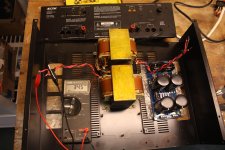
Here are a few photo's of my project showing the dual transformers and the secondaries. They show voltage of ~34.5V (AC) from either primary with nearly 70V across both. Both transformers read the same.
Here are a few photo's of my project showing the dual transformers and the secondaries. They show voltage of ~34.5V (AC) from either primary with nearly 70V across both. Both transformers read the same.
Last edited by a moderator:
 Steve, please DO NOT copy and paste images into the reply window. This results in 100s of 10000s of lines of ASCII gibberish that takes a lot of work to fix.
I've done the clean up.
Please use the Attach function instead.
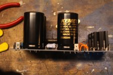
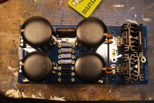
Here are a couple of photo's of the completed half of the power supply. I applied jumper leads to one of the primaries and another to ground. DC voltage was greater than +40V however there was a buzzing sound. I unplugged and then plugged back in. Voltage started to fall, very slowly. When I plugged back in, I discovered that the main fuse (as shown on back panel) had blown. Not sure if that's connected to the buzzing.
Anyway, I don't have another 8A glassine fuse to try again. I did put a 6A fuse in just to see if the transformers were OK. They are. Nothing seems to be harmed.No smoke. Now heat. No burning smell. Not sure why fuse blew so quickly.
The test connection was jumper from one red secondary to AC1A (34.5V) on PSU board. Center Tap (black) from transformer went to ST1N1 on PSU board.
Sorry, I didn't realize. I just posted another like the first. So Sorry!
Where is the "Attach Function"? I just see "Insert Image" function and it directs me to use a URL address. Not sure how that works.
Where is the "Attach Function"? I just see "Insert Image" function and it directs me to use a URL address. Not sure how that works.
My Dual Transformer Project
Here are a couple of photo's of the completed half of the power supply. I applied jumper leads to one of the primaries and another to ground. DC voltage was greater than +40V however there was a buzzing sound. I unplugged. Voltage started to fall, very slowly.I then plugged back in. I then discovered that the main fuse (as shown on back panel) had blown. Not sure if that's connected to the buzzing. I think the buzzing was probably the transformer.
Anyway, I don't have another 8A glassine fuse to try again. I did put a 6A fuse in just to see if the transformers were OK. They are. Nothing seems to be harmed.No smoke. Now heat. No burning smell. Not sure why fuse blew so quickly.
The test connection was jumper from one red secondary (34.5V) to AC1A on PSU board. Center Tap (black) from transformer connected to ST1N1 on PSU board.
Attachments
Last edited:
My Dual Transformer Project
Here are a couple of photo's showing the dual transformers and the secondaries. Secondaries display voltage of ~34.5V (AC) from either primary. Both transformers read the same.
If I measure across both primaries, it is nearly 70V (AC).
Here are a couple of photo's showing the dual transformers and the secondaries. Secondaries display voltage of ~34.5V (AC) from either primary. Both transformers read the same.
If I measure across both primaries, it is nearly 70V (AC).
Attachments

Last edited:
Your terminology is still a bit off. You keep using the word "primary" but I think what you mean is the ends of the secondary of your transformers, which happens to be center tapped. Primary usually refers to the mains side of a transformer.
The transformers, if they came from an Adcom gfa2535, did indeed have center tapped secondaries. As you measured, the total secondary voltage is about 70VAC or 35VAC on either side of the tap.
In the Adcom, these were used with a full-wave bridge rectifier with the center tap connected to ground. This is referred to as a split supply. The resulting DC output voltage is about +/- 47 VDC. (35VAC x 1.4 - about 1 Volt rectifier drop).
The universal PSU boards with the rectifiers were meant to be powered by transformers with 2 independent secondaries (not center tapped). If you just connect your transformer to the bridge and leave the center tap open, you end up with about 97 Volts coming out of the bridge - way too much!!
That does not mean you can't get this to work. You just need 1 bridge, not two, and two PSU boards - one for the positive rail and one for the negative rail and connect the transformer center tap to the common ground. This will give you ~+/- 47 VDC.
See this post by Mark Johnson earlier in the thread: diyAudio Power Supply Circuit Board v3 illustrated build guide
Clear as mud? 😀
Thanks. I gave the project a bit of thought today on when I was out for a walk.
Yes, my thinking was flawed when I thought I could somehow create a dual power supply (one for each channel) using the universal power supply. But, having purchased the Universal PSU board and components, I'd like to use them for this project!
Here's the alternate plan I cooked up in my head while out on my walk. What if I were to connect, in parallel, the secondaries of the two transformers and connect the resulting paralleled secondaries to the completed Universal PSU boards? It wouldn't be a dual-mono design like I imagined but I think it would work. I've already researched how to make sure the transformers are in phase with each other and done that test so that I don't burn the transformers up.
Or are you saying I can't use the Universal PSU with a these center-tap transformers and that I need different PSU boards and a single bridge rectifier? I will also read the Mark Johnson post you pointed me to.
Thanks for the help!!
Last edited:
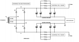
Maybe this diagram will help. Basically, you will only need a single rectifier board to supply the 2 PSU filter boards. You will need to re-wire it since you have it attached to one of the PSU boards already.
The center tap of the transformer must be connected to the common ground. I am referring here to a "star" ground where all amplifier ground returns should be connected at a single point (note: this not the same as chassis ground - you should install a ground lift thermistor between chassis and star ground).
If you want to go dual-mono, you will need another pair of Universal PSU boards and another rectifier board.
If you want to stay with a single pair of PSU boards, you COULD parallel two transformers to get more current, but be extremely careful about the phasing of the primaries and secondaries, otherwise, you risk blowing them up.
Attachments
Last edited:
- Home
- Amplifiers
- Power Supplies
- diyAudio Power Supply Circuit Board v3 illustrated build guide