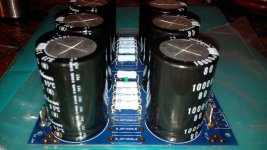
Another PSU lives! This one is for my Honey Badger, which is turning into a world record for time taken to build 😛 .
You think you are the only one, there are other contenders too 😉
You think you are the only one, there are other contenders too 😉
Lol, home renovations are taking over my life. The good news is that I will have an 1100sq foot undeveloped basement for a workshop when it's all done!
Hello
i am using this psu for F5. My R9 and R10 bleeder resistors are 22k but i saw someone using 2.2k. The BOM indicates 4.7k to 22k. Any problem here?
any need to install R11 and R12 output snubber resistors and output snubber capacitors (0.1nf) ?
I am using the IXYS diodes instead of the monolythic. I think there is no problem here.
For now i only have 8x10000uf/35v capacitors. Can i use them for testing and upgrade later?
This is for a simple F5.
thank you
22K bleeder is fine, all they do is discharge the PSU caps after turn-off.
No snubber capacitors.
8x 10,000uF may be enough. It will be fine for testing.
No snubber capacitors.
8x 10,000uF may be enough. It will be fine for testing.
i've read the last few pages and i am confused in the CL-60 department. I asked on another forum but i think here is more adequate.
So, my transformer is single primary 240v - 400va, and 2x18v secondary (toroidy). I have to install 2 CL-60 (or other? don't know) in series with hot or neutral. That was what andrewt said, i think. If that's right, what fuse do i have to use? and where the ceramic capacitor goes? what's his job?
sorry, i'm trying to understand the "equation" instead of repeating it and make serious mistakes.
thank you
Fuse rating is VA/Vac
for 400VA running on 230Vac you need a 1.7A or less.
Try a T2A or T1.6A
To prevent that fatiguing and eventually nuisance blowing after repeated cold starts you need to insert a current limiter in the primary circuit.
The 10R of a single CL60 with 230Vac driving current into the not yet started transformer is not doing a big heap of current limiting.
I would use 60r to 80r of resistance to limit the starting current to about 3 to 4A
I find that does not blow a T2A fuse.
You can try lower than 60r and see how long a T2A lasts. Maybe you'll get years of use.
Fuse rating is VA/Vac
for 400VA running on 230Vac you need a 1.7A or less.
Try a T2A or T1.6A
To prevent that fatiguing and eventually nuisance blowing after repeated cold starts you need to insert a current limiter in the primary circuit.
The 10R of a single CL60 with 230Vac driving current into the not yet started transformer is not doing a big heap of current limiting.
I would use 60r to 80r of resistance to limit the starting current to about 3 to 4A
I find that does not blow a T2A fuse.
You can try lower than 60r and see how long a T2A lasts. Maybe you'll get years of use.
No need for the cap mentioned?
Ok, i read on another thread that the ceramic is needed. I will post pictures of my amp. I have doubts on wich wires must be twisted and i really don«t understand how to do a MAG. I think the F5 v3 boards help in that but i just want to be sure. Thank you for your help
Is this ok?
The word "transformador" = transformer
The word "Neutro" = Ground
The word "Fase" = Line
The word "Terra" = earth
my transformer is a toroidy and it has a earth wire
The word "transformador" = transformer
The word "Neutro" = Ground
The word "Fase" = Line
The word "Terra" = earth
my transformer is a toroidy and it has a earth wire
An externally hosted image should be here but it was not working when we last tested it.
sube fotos
That doesnt look right to me. Don't hook it up yet!
Your transformer has an earth lead? I think that is probably shielding.
Can you post a photo of your transformer?
What voltage mains are you on?
Your transformer has an earth lead? I think that is probably shielding.
Can you post a photo of your transformer?
What voltage mains are you on?
Yes, my transformer has an earth lead. I'm on 220-230v mains. I have two thermistors instead of one because of their resistance. It was an advice from a user. I really don't know what i am doing. Just trying to imitate and trying to no t blow everything.
Build up a Mains Bulb Tester.
Use that to power on every new or modified mains powered project.
That will prevent you damaging your transformer.
Use that to power on every new or modified mains powered project.
That will prevent you damaging your transformer.
Have read some of you previous post.
That ceramic cap looks like its meant to stop arcing on the power switch and RF filtering. You have to use an x rated capacitor. I'm not sure whether x2 will be enough or if it has to be x1. I can't tell from the photo whether that's the case or if it's a standard ceramic cap.
Just checked mine. I have the soft start board and it's a 1uf x2 and it's about an inch wide.
The reason for x caps is in the position they're in, they take a battering.
Edit ****
If they fail they have to fail in a way where they dont catch fire , explode or cause a dangerous condition.
X are used across power lines
Y are used between power and ground. If this fails it has to not short out otherwise your chassis can become live. You can't use an x cap here.
**** End edit
I see your using a couple of cl60s in series. I would use a longer connector block and use an extra connector to hold where you've soldered the cl60s together so they're not floating loose.
Last edited:
Just found this
ABC's of Safety (Interference Suppression) Capacitors for Tube Radios
I wasn't quite right about x caps. This artical will explain better.
I have just edited my previous post
ABC's of Safety (Interference Suppression) Capacitors for Tube Radios
I wasn't quite right about x caps. This artical will explain better.
I have just edited my previous post
Last edited:
I can't read your image, it's not clear.yes. i already have a bulb tester on the bench. but is my image correct?
You need to connect the PE wire direct and permanently to chassis. Soldering is not allowed: A permanent mechanical fixing.
Your Live feed goes straight into a mains fuse.
Then you can fit your other bits and pieces after the fuse.
Do not fit a suppressor across the switch. This leaks when the switch is off, leaving the internal circuits Live.
Fit the suppressor across the load as early in the wiring as possible.
Keep all the pairs of Flow and Return wires close coupled, or twisted, to minimise interference.
Insulate all bare mains wiring/terminals.
Consider adding double insulation to all your mains wiring and fixings/termination.
use a three terminal strip. the junction between the two Power NTCs going into one terminal to be mechanically secured. The NTC can run very hot. You don't want the solder becoming weak.I see your using a couple of cl60s in series. I would use a longer connector block and use an extra connector to hold where you've soldered the cl60s together so they're not floating loose.
Last edited:
- Home
- Amplifiers
- Power Supplies
- diyAudio Power Supply Circuit Board v3 illustrated build guide