In a properly performing amplifier, the amplifier circuit will drain the PS capacitors at power off. The main purpose of the bleed resistor is to bleed the PS capacitors after power off if the PS is powered on without the amplifier circuit connected or a if failure occurs in the amplifier circuit that stops the circuit from drawing power. This is where a LED on the PS board is useful to indicate charged capacitors on the board.

I think (at least to me) that it's important to separate the distinction of the Universal PSU boards which can be used for a great number of things; one of which is a "First Watt" PSU. You're (I think) referring to the use of CL-60s (a brand / specific model of an NTC Thermistor) in a number of First Watt PSU designs. They're used both as inrush current limiting devices and ground lifts. That may be the confusion. The part name doesn't dictate its function even though a common use for that part is as an inrush current limiter. Heck I think CL may stand for, current-limiter. I can't be certain, but the lore of the internet and/or spec sheets might have mentioned it somewhereThanks for the quick replies!
Right. I suppose NTC would have been the right term to use. In various builds of the DIY PSU, I've seen and used a CL-60 here, following other's experience.
Matter of preference only. I personally use them, but others don't...Why wouldn't you want them? They're there to gracefully drain the CAPs when amp turned off off and I assume, when on, are such a high parallel resistance that current prefers to go to the rails for the amp to use.
By the way, I'm welcoming another M2X to the world this afternoon.
Wooooooooo! Congrats.
There are some that might chime in and say that's unwise, so beware potential (well-reasoned) backlash. If you know the risks and accept them, the choice is yours.As I had only enough CL-60s for the primaries, I put in a 10 ohm 3 watt between PSU ground and chassis.
Either way, congratulations.

Yes. My initial question, better put, is "why use an NTC/thermistor for a ground lift?"They're used both as inrush current limiting devices and ground lifts. That may be the confusion
Oh, this applies to sooooo many things in life. "Why did they call it 'X' if it does almost nothing 'X'-like?" Such is life.The part name doesn't dictate its function
Thanks all.
M2X is stuck at 50mV offset, with its adjusting RV1 at its limit, so I'll need to play with my R6 and Rv1 value. But 50mV is close enough to plug into speakers in the mean time.
Rather than scratch at that old wound... I might ask... why might that part be better suited for the job than a 3W resistor? What might be more of a belt and suspenders approach (like the F5T-style ground lift)?Yes. My initial question, better put, is "why use an NTC/thermistor for a ground lift?"
Truly, I'm not skilled enough to answer your question directly, but I've read 100s of posts around that specific subject. I try to understand both the function of the part in its direct sense (ground lift) around what may happen in various fault situations (however likely or unlikely they may be)... ultimately I trust the gentleman that designed the circuits and chose to put those parts in that application in commercial products.
Very little help, I know, but that's my general thoughts.
🙂Oh, this applies to sooooo many things in life. "Why did they call it 'X' if it does almost nothing 'X'-like?" Such is life.
Wooooooooo! I think you'll love it.M2X is stuck at 50mV offset, with its adjusting RV1 at its limit, so I'll need to play with my R6 and Rv1 value. But 50mV is close enough to plug into speakers in the mean time.
M2X is stuck at 50mV offset, with its adjusting RV1 at its limit, so I'll need to play with my R6 and Rv1 value. But 50mV is close enough to plug into speakers in the mean time.
Go to M2x Forum thread, search for Blasphemous Heresy and tell the search box to examine "this thread only". It's on the first page of that thread , i.e., the first twenty posts.
Oh, I'm well aware of the blasphemy and this is the perfect occasion of sin. 🙂
I just have to see what else I have in my mystery box-o-resistors as replacements to get me a bit more wiggle room.
But it will have to wait until tomorrow. I'm tuckered out.
I just have to see what else I have in my mystery box-o-resistors as replacements to get me a bit more wiggle room.
But it will have to wait until tomorrow. I'm tuckered out.
Yes. My initial question, better put, is "why use an NTC/thermistor for a ground lift?"
Because it can handle all the fault current, if needed. A resistor likely can't.
Also, the NTC will be a lower resistance in normal operation once everything is warmed up, where the resistor will be increasing it's resistance.
That said, your resistor ground lift will work nicely for testing, but I'd suggest changing it before declaring it completed.
As for offset, 50mv is totally fine. You'll only need to tweak your R6 a little bit to have enough throw on the pot to get that to zero.
Last edited:
I may have goofed. these are the input snubbers i purchased.
I referenced the Quasimodo test thread for my Antec - 3218
CX- 0.01uf
CS- 0.15uf
both rated at 200v. can i use these if i can make them fit? if i can am i sacrificing anything? if i can not use them please let me know what i should have purchased. (Aleph J build)
thank you 🙂

I referenced the Quasimodo test thread for my Antec - 3218
CX- 0.01uf
CS- 0.15uf
both rated at 200v. can i use these if i can make them fit? if i can am i sacrificing anything? if i can not use them please let me know what i should have purchased. (Aleph J build)
thank you 🙂
You can use them. Depending on other components used, and if it's too tight a fit, you might mount them on the 'bottom' of the board.
If you choose not to use them and/or or feel strongly about mounting them on the 'top' of the board, you may like something like...
https://www.mouser.com/ProductDetail/871-B32529C3154J289
and
https://www.mouser.com/ProductDetail/EPCOS-TDK/B32529C3103J?qs=CveI/UwZDBL3iRjKBP7New==
Others may have better suggestions.
Cheers.
Great. I think i will try puzzling them into the top and if it becomes too much a challenge, under they go!You can use them. Depending on other components used, and if it's too tight a fit, you might mount them on the 'bottom' of the board.
If you choose not to use them and/or or feel strongly about mounting them on the 'top' of the board, you may like something like...
https://www.mouser.com/ProductDetail/871-B32529C3154J289
and
https://www.mouser.com/ProductDetail/EPCOS-TDK/B32529C3103J?qs=CveI/UwZDBL3iRjKBP7New==
Others may have better suggestions.
Cheers.
Thank you for the links
The bottom has better accessability. You don't have to remove the heatsink/diode in the event that you want to change the value etc. It is already a tight fit to begin with.
^  Exactly. Many people use the same rectification / filter boards with a few different transformers for various reasons. Makes like much easier, IMO.
Exactly. Many people use the same rectification / filter boards with a few different transformers for various reasons. Makes like much easier, IMO.I placed the capacitors underneath the board. That was good advice.
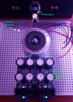
I am having trouble understanding what i need to do to properly ground the PS. I have seen other builds without terminal blocks while placing the thermistor directly onto the IEC. Will my 5A 10ohm thermistor work in this position?
In the picture the ground from the transformer (purple) goes to the ground on the IEC and from the IEC is connected via starnut to the chassis.
Do i need to run wire from this starnut to a ground on the PS or can i create another starnut ground near the PS with a short run of wire.
I have an extra 5A 10ohm thermistor, could/does this need to be used between the starnut ground and wire to the IEC like in the picture?
Attachments
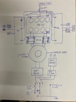
The thermistor as you sketched it doesn't seem to be correct (IF I got it right)—
You need one CL60 to connect the transformer to the IEC (from hot to one primary wire)
You need another CL60 as a ground-lift, through which you connect the Capacitor-bank to the star-ground...
...
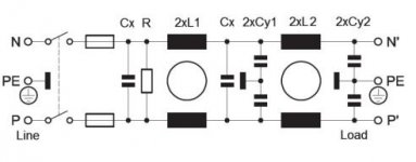
The place where you put the CL60 is the place to put in a security-cap (to avoid sparks on turn-on/off)
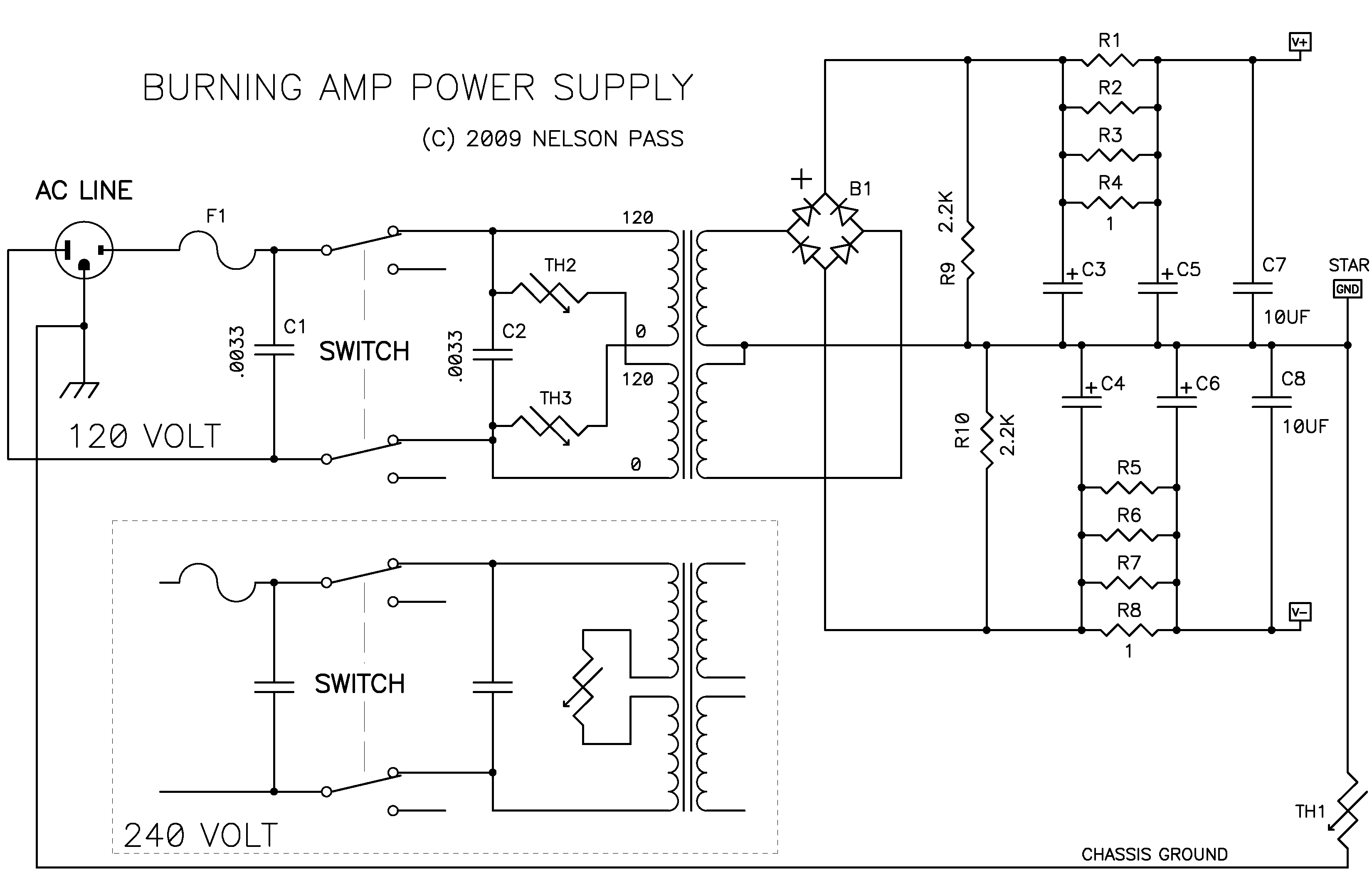
(here's some brain-food 😉 https://www.diyaudio.com/archive/article-images/ba1/BA-1-PS.png )
You need one CL60 to connect the transformer to the IEC (from hot to one primary wire)
You need another CL60 as a ground-lift, through which you connect the Capacitor-bank to the star-ground...
...
The place where you put the CL60 is the place to put in a security-cap (to avoid sparks on turn-on/off)
(here's some brain-food 😉 https://www.diyaudio.com/archive/article-images/ba1/BA-1-PS.png )
addendum, didn't find itbrain-food
Attachments
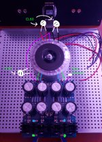
I think i understand what i need to do. How does this look?
You said one CL60 connecting the transformer to the IEC, as in i would need a single CL60 between one positive wire and the IEC hot, while no CL60 on the negative side?
I believe the IEC i am using has built in safety capacitors (schaffner FN9290-10-06) too bad it doesn't have a couple CL60's in there 😉.
Attachments
You’re almost there!
1 CL60 at IEC
PSU ground: only 1 wire, with CL60, goes to star-ground
(a second wire to starground—without CL60—would just short it…)
Look at 6L6‘s guide (it’s the F4 but the same here, and to make his comment more precise, it is the only connection from the PSU and amp-board to the chassis! )
(I wasn‘t consequently following the ground-star principle but made several independent connections: one from the IEC, one from the tranny, and one, with CL60, from the PSU. Works.)
Last edited:
Another thing, make sure you get one cl60 on each primary of the transformer. Each primary has a red and black wire. One of those wires will connect directly to either the hot or neutral. The other wire will go through a CL-60 to reduce the inrush. Otherwise half (one polarity) of your power supply wouldn't have any in Rush protection.
You don't want to tie the ground from the power supply board to the chassis at all. The point of the CL 60 on the ground connection leading to the power supply board is not to reduce the inrush but rather it is there too suppress noise. It will have a resistance of around 20ohms cold and once power goes through it, the CL60 thermistor warms up and reduces it's resistance to about 7-10 ohms give or take.
Another suggestion, hit the top so the jumpers with some solder. Just gives it a little bit better of connection.
Ah my bad. Being in 230volty switzerland, I didn‘t even think there‘s countries with anything else…
- Home
- Amplifiers
- Power Supplies
- diyAudio Power Supply Circuit Board v3 illustrated build guide