Hi
.In the instructions it states that 0.6 volts is the optimum figure, but also 0.4v may be acceptable. Have you tried different voltages and what was the effect on sound quality.
Thanks!
.In the instructions it states that 0.6 volts is the optimum figure, but also 0.4v may be acceptable. Have you tried different voltages and what was the effect on sound quality.
Thanks!
Broadly speaking, more bias sounds better. Easy enough to try though, give it a go and see what you think. 
Thanks for the reply.
Found something interesting, my transistors are running a little hot so i put a strip of copper over the transistor and bolted it down, found that the transistors are running much cooler with a heatsink above them as well.
Basic physics, heat rises.
Found something interesting, my transistors are running a little hot so i put a strip of copper over the transistor and bolted it down, found that the transistors are running much cooler with a heatsink above them as well.
Basic physics, heat rises.
About the psu, When i build a psu i just use a transformer>bridge rectifier>smoothing caps and it works fine.
In the pass design there is R10 2.2k, what does R10 do, is this not just wasting power.
Also there is R5 - R8, what do these do.
I have heard of people placing resistors across caps to help them discharge, but not in this manner.
Thanks!
In the pass design there is R10 2.2k, what does R10 do, is this not just wasting power.
Also there is R5 - R8, what do these do.
I have heard of people placing resistors across caps to help them discharge, but not in this manner.
Thanks!
FWIW, heat doesn't rise. Hot air does. Heat spreads out uniformly in all directions.
The 2K2 resistors are bleeders (for discharge when the amp is turned off). R5 through R8 are the 'R' in the middle of a CRC filter, which is much more effective than a C filter. A C filter largely just shifts the phase and frequency; an RC filter actually damps the waveform.
Cheers,
Jeff.
The 2K2 resistors are bleeders (for discharge when the amp is turned off). R5 through R8 are the 'R' in the middle of a CRC filter, which is much more effective than a C filter. A C filter largely just shifts the phase and frequency; an RC filter actually damps the waveform.
Cheers,
Jeff.
Hello,
I would like to build an F5 V3. I have a little question regarding output mos fet that are in the bom notified IRFP9240/IRFP240 and those wich are in the scheme FQA19N20/FQA12P20 ( Firstwatt F5 amplifier v3 - diyAudio Guides) . What is really provided with th F5 parts Kit?
Thanks
I would like to build an F5 V3. I have a little question regarding output mos fet that are in the bom notified IRFP9240/IRFP240 and those wich are in the scheme FQA19N20/FQA12P20 ( Firstwatt F5 amplifier v3 - diyAudio Guides) . What is really provided with th F5 parts Kit?
Thanks
Hi!
The power supply has 0.47 ohm resistors between two of the caps, is there anything to be gained by adding resistors between the rest of the caps in a similar manner to help smooth the supply further, would this yield any sonic benefit.
Thanks!
The power supply has 0.47 ohm resistors between two of the caps, is there anything to be gained by adding resistors between the rest of the caps in a similar manner to help smooth the supply further, would this yield any sonic benefit.
Thanks!
Sdfrance- IRFP240/9240
Goodguys - the resistors are in between the two banks of capacitors, not between two of the eight. So in a manner, they already are between all the caps.
Goodguys - the resistors are in between the two banks of capacitors, not between two of the eight. So in a manner, they already are between all the caps.
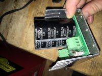
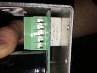
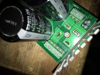
I have these spare PSU regulators (2 total) and I’m wondering if I could use two of them for an F5 or even An F4 or F6.
Each cap is 22000uf and two are on each board (44000 per rail). I’ll have to pull out the resistors to get the exact resistances but there are two on each board. There are bridge rectifiers attached Rated at 35V and 1.2A (KBPC3510).
Would I just need to wire the grounds together?
And what resistor values would I need to have total for each board?
Attachments
Last edited:
I just did a test of the completed "Universal Power Supply". My first PSU; no smoke! I used the AS-3220 toroidal transformer. With no load, I'm reading 28.9V between GND and V+ although specs on the transformer from the manufacturer are "300VA 20V" is this normal? Same for GND to V-
Also, it takes several minutes for the caps to drain. I tested R9 and R10 before installation and they are the prescribed 2.2k. Aren't those resistors designed to drain the caps? or is this a normal time period to reduce wasted power while the amp is on? (AS-3220 - 300VA 20V Transformer - AnTek Products Corp)
Also, it takes several minutes for the caps to drain. I tested R9 and R10 before installation and they are the prescribed 2.2k. Aren't those resistors designed to drain the caps? or is this a normal time period to reduce wasted power while the amp is on? (AS-3220 - 300VA 20V Transformer - AnTek Products Corp)
Last edited:
During quarantine I've had the chance to get somewhere with my project.
Circuit boards are done except for the resister or LED that doesnt come with the kit.
In the instruction they mention the use a 15K resistor.
Would it be ok to use this LED: ELM15755GD Bivar | Mouser Espana
And a carbon film resistor of 15K (1/2w)?
Also, before ordering, do you think this transformer would be a good choice?
http://www.sedlbauer.de/media/ringkerntrafo_datenblatt_826053.pdf
You need to buy a transformer of 0-18v/0-18v or 0-20v/0-20v.
When you rectify AC to DC the voltage increases by 40%.
Your led and resistor will work well.
When you rectify AC to DC the voltage increases by 40%.
Your led and resistor will work well.
Can resistors 3,4,5, and 6 (100 ohm) be replaced with 110 ohm 3 watt in the F5?
I have a lot of extras in my stash I need to use.
I have a lot of extras in my stash I need to use.
Trying to get used to how hot the transistors are, as i have only used class-a/b amplification before. Can you tell me does this reduce transistor life. Even with good heatsinking it feels unnatural.
Also, if i reduce the bias how will that affect the end sound coming outof the speakers what changes will i notice? Loss of accuracy, distortion.
Thanks
Also, if i reduce the bias how will that affect the end sound coming outof the speakers what changes will i notice? Loss of accuracy, distortion.
Thanks
Can you keep your hands on the heatsinks for 10+ seconds ? If yes, you have nothing to worry about.
Sonically, more bias is better.
Sonically, more bias is better.
The power supply voltage is +/- 27 volts, i made the voltage a little higher than recommened to account for voltage sag but there does not appear to be any, would dropping it down to 20 volts reduce the amount of heat producded by the transistors
As you mentioned you are concerned about negative affect of high heat on the components, this may reassure you... Specs on the mosfets say: "Operating Temperature -55°C ~ 150°C"Is the board affected by psu voltage.
Thanks
I suggest you make sure the mosfets are mounted properly to your heatsinks with keratherm or similar, then use a point-to-test IR temp meter to check they are within the suggested operating range. Mine get up to around 70 to 80 C.
- Home
- The diyAudio Store
- diyAudio F5 Build Guide