You now have a attenuation of -32.65db should be 6 db lower as the qa401 adds 6 so you want -28.65 or there aboutsWorked the divider out and the readings just didn't seem right. I checked everything and then had a thought and check my bench supply. I have little to no neg output there.
I had an old project one i made in EET some 35yrs ago. i fired it up, sure enough stil worked. I tweaked it up to -+ 12v and hooked everything back up.
Now I get 279.69mV which is about what the reverse divider equation came out to as well.
Last edited:
Let me double check my spreadsheet using your numbers and come back to you. PM me your email address again pleaseThe values are right... so I don't know what the deal is...
You should also make one for your loopback test to attenuate -0.5dBv output to -5dBv inputi now have a board, or two extra if someone else needs one let me know.
You're using the Honeybadger frontend to drive ten pairs of output devices? What's your intended rail voltage?
Best regards!
Best regards!
i pulled a bone head move when doing some testing... I hit the QA testing for a pulse and instead it stayed on steady input. I was moving some leads around and R25 went up like a smoke grenade. 😛 Dumbazz move on my part, but I know if R25 smoked there was a reason, so just replacing that is unlikely to fix the issue.
What all should I test before firing this thing up again?
What all should I test before firing this thing up again?
Attachments
So far Q9 was toast and replaced as well as the R25 and R14 took a lot of heat from R25. It measured okay, but I'm there so might as well be safe. Going forward and back testing looking for more. By some readings I'm getting there are more transistor issues.
You're using the Honeybadger frontend to drive ten pairs of output devices? What's your intended rail voltage?
Best regards!
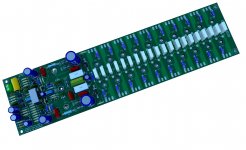
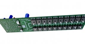
this is a 9pair output in a triple Darlington configuration, +-85 volt rails..
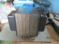
this is where i am using my monster power traffo that i made....
i have four 68mf/100vdc cans from ApexJr for psu duties...
Attachments
Confirm any 1A diode for D1-D2 just make sure they fit the holes... correct?
JT
yes...i did not have problem with mine, the holes were big enough..
So far Q9 was toast and replaced as well as the R25 and R14 took a lot of heat from R25. It measured okay, but I'm there so might as well be safe. Going forward and back testing looking for more. By some readings I'm getting there are more transistor issues.
do not forget that dim bulb tester, that is a real life saver...
i pulled a bone head move when doing some testing... I hit the QA testing for a pulse and instead it stayed on steady input. I was moving some leads around and R25 went up like a smoke grenade. 😛 Dumbazz move on my part, but I know if R25 smoked there was a reason, so just replacing that is unlikely to fix the issue.
What all should I test before firing this thing up again?
with the aid of a dim bulb tester, two steps, first is output offset dco or dc output adjustments, + -100 millivolt is acceptable, but of course closest to zero is what we aim for, the desiderata …..
second is standing output current adjustments, you may notice your dim bulb getting brighter if you over do your bias adjustments...when you are satisfied that there is no crossover distortion at the 1 watt/8 ohm levels then you are done...actually if the dim bulb tester does not turn full bright, you got a viable amp now....and can wean the amp off it for the crossover distortion testing with a scope...
when all okey, you can then proceed to listening tests....
now to your question on r25, it smoked when there was excess voltage across it, the base of the q9 was pulled to ground when poking around....so i will replace q9 and r25 and maybe the VAS itself...then proceed over..
Attachments
Last edited:
Thanks for the input Tony. 🙂 I've thought the same thing and have been working in that direction. I'll post some thoughts and ask for direction tomorrow. It's looking good, but I'm seeing some differences in resistance from the good channel to the one that had problems. I've solved some of those issues, but not all. I don't want to power it up unless I think it's right, even with a bulb. Some of the base-emitter-collector resistances don't jive with the good side.
Anyway, thanks again, i'll get back to it when i get some data I can put down and be more specific.
jT
Anyway, thanks again, i'll get back to it when i get some data I can put down and be more specific.
jT
Last edited:
welcome.....for grading ang matching trannies i use this tester....
this tester can give you pinouts, Hfe and tells you what device you have or if it is bad....
https://www.lazada.com.ph/products/...MI0P3-la2O8QIV-Z1LBR2ILwojEAQYAiABEgJzaPD_BwE
this tester can give you pinouts, Hfe and tells you what device you have or if it is bad....
https://www.lazada.com.ph/products/...MI0P3-la2O8QIV-Z1LBR2ILwojEAQYAiABEgJzaPD_BwE
Last edited:
Hi Tony,
Really? That thing?
Besides, you cannot properly match transistors unless they are at the same exact temperature.
Whatever ....
Really? That thing?
Besides, you cannot properly match transistors unless they are at the same exact temperature.
Whatever ....
Hi Tony,
Really? That thing?
Besides, you cannot properly match transistors unless they are at the same exact temperature.
Whatever ....
yes its that thing.😀...
even tells me if i have a depletion or enhancement mosfets...what is not to like?
worked for me and a lot of others, it may work for you....😀
Hi Tony,
I have a couple different versions of that thing. It doesn't measure leakage properly as it isn't sensitive enough.
I don't use them anymore as my old tools told the truth and were more accurate.
If you are attempting to match transistors, the two must be at the same temperature. Period. So make your own diff pair circuit up. Measure the difference between collector voltages using the meter as a null indicator.
When you don't know any better, it does appear to work well. That's the danger of those silly things. They work fine in a gross sense. Just like the beta tester in a cheap meter. Why ever would you expect them to be accurate??worked for me and a lot of others, it may work for you....
- Home
- Amplifiers
- Solid State
- diyAB Amp The "Honey Badger" build thread