Yes, that method is as sensitive as he claims. I had trouble with it due to more or less dirt/corrosion/oils on the test leads, measuring points, and wires; SO, I also had to clean all the contact points with simple green and alcohol, several times, before it made sense. It also took Firm pressure on the test leads (and steady hands) to achieve a repeatable measure.
Same troubles as trying to measure (and match) very low value emitter resistors and pi filter resistors. That can be done, but not in a hurry. So, I think it is for use when you really really need to know. And, indeed you do find out.
Same troubles as trying to measure (and match) very low value emitter resistors and pi filter resistors. That can be done, but not in a hurry. So, I think it is for use when you really really need to know. And, indeed you do find out.
Power supply for HB
This is my first post, please forgive my ignorance! I was considering building the 'Honey Badger' for use as a subwoofer amp. That being said, I've never built an amp of any kind before. I've made plenty of circuits and would be perfectly comfortable building this though, especially seeing how complete the guide is!
My questions are this:
Would it be appropriate to use this as a subwoofer amp, and with a 4 ohm driver?
Should I even attempt this? 🙂
It was the HB or something like this: https://www.parts-express.com/dayton-audio-spa250-250-watt-subwoofer-plate-amplifier--300-803 - I can only assume the HB would be 100% more reliable, as well as sound 10x better?
Would I still use the 800va 2x 45v transformer that's recommend even if I'm only building a single HB? If so, how would I wire both secondaries into the PS board/softstart?
How many/what size caps would I use in the power supply, assuming I would be using the 'Universal v3' PS? I see 4x 10,000uf per rail (but what is a rail? each secondary?; I've never worked with AC)
HB is perfect for a sub. Lower voltage rails for a 4R driver (50-60V) and
MG-6330/MG-9410 semelab ... http://products.semelab-tt.com/pdf/bipolar/MG6330%20MG6330-R.pdf .
For subwoofer duty.
Current- larger VAS heatsink (R27 = 68R = 9.5ma current) ....
----- Better for the "droop" of an EF2 driving a "hungry sub"----
Compensation- omit R24 / jumper C7 / 100pF for C8.
---- This is a sub amp , HF performance does not matter. ----
Input filter - optionally , C2 can be larger 470-680pF .
If dayton (below 1) , rates THAT as a 250w 😱 .... a 3 pair HB (or mine- below 2)
would be 400W+ !! You would also need a 400VA-600VA / 40-0-40Vac trafo
(40= 54Vdc - 45 = 60vdc) and 25K - 32Kuf / 80+ Volt capacitance.
A cheap ebay subwoofer low pass filter can be used for level Fc cutoff.
PS - my sub amp posted is the exact same as HB (wolverine) , with the above posted changes - It really works .
Unfortunately , the HB can't fit those big MT-200 sanken's. 🙁
EDIT - Dayton does give a lot for 130$ , a sub badger will cost 200+ $$ !
OS
Attachments

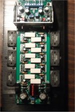
Last edited:
HB is perfect for a sub. Lower voltage rails for a 4R driver (50-60V) and
MG-6330/MG-9410 semelab ... http://products.semelab-tt.com/pdf/bipolar/MG6330%20MG6330-R.pdf .
For subwoofer duty.
Current- larger VAS heatsink (R27 = 68R = 9.5ma current) ....
----- Better for the "droop" of an EF2 driving a "hungry sub"----
Compensation- omit R24 / jumper C7 / 100pF for C8.
---- This is a sub amp , HF performance does not matter. ----
Input filter - optionally , C2 can be larger 470-680pF .
If dayton (below 1) , rates THAT as a 250w 😱 .... a 3 pair HB (or mine- below 2)
would be 400W+ !! You would also need a 400VA-600VA / 40-0-40Vac trafo
(40= 54Vdc - 45 = 60vdc) and 25K - 32Kuf / 80+ Volt capacitance.
A cheap ebay subwoofer low pass filter can be used for level Fc cutoff.
PS - my sub amp posted is the exact same as HB (wolverine) , with the above posted changes - It really works .
Unfortunately , the HB can't fit those big MT-200 sanken's. 🙁
EDIT - Dayton does give a lot for 130$ , a sub badger will cost 200+ $$ !
OS
OS, what Iq would you run your outputs at for your sub amp
OS, what Iq would you run your outputs at for your sub amp
Considering just needing 20-100hz , would we even hear X-over distortion ?
But , still ... I would subjectively know it existed. 😀
Typically , I run ON 0281/0302's 60-70ma each.
In OEM's , I see the recommended Sanken output bias a little lower at 50ma.
One , a Sansui ... even at 35ma !
This is the first Sanken output stage I've DIY'ed. 😕
OS
Transformer
Thank you for the reply! I would much prefer to make this amp over purchasing the Dayton. For many reasons!
One question: how would I wire in the transformer? Would I wire the secondaries in parallel? Assuming I would be getting the AN-6440
Or just use one secondary for the power supply and leave the other disconnected?
Nope ! primaries in parallel for US 115Vac. Secondaries in series for 40-0-40Vac.
This would give @ 55-0- ... -55V(DC).
AN-6440 also has the 12/18V secondaries ... run them in series for your
sub active filter. Even unbalanced (16 and 23V dc) , those extra secondaries
would work with the standard 7812/7912 regulators in your typical ebay
sub filter. 🙂
PS - that's quite a transformer . At 4R , it would run a dayton 10/12" HO at 400+W- easy!
Definitely get the Semelab bad-**** output devices for this setup !!
OS
Last edited:
I'm having a hard time sourcing the Semelabs 🙁
I will go less on the transformer if you recommend it, don't want to blow anything up! I would like to shake my living room at 25hz though! Sorry for being a noob!
I think this filter looks ok... OPA2132 Subwoofer Low Pass Circuit Amp Filter Board DIY AC 6 13V DC±9 18V | eBay
I will go less on the transformer if you recommend it, don't want to blow anything up! I would like to shake my living room at 25hz though! Sorry for being a noob!
I think this filter looks ok... OPA2132 Subwoofer Low Pass Circuit Amp Filter Board DIY AC 6 13V DC±9 18V | eBay
I'm having a hard time sourcing the Semelabs 🙁
I will go less on the transformer if you recommend it, don't want to blow anything up! I would like to shake my living room at 25hz though! Sorry for being a noob!
I think this filter looks ok... OPA2132 Subwoofer Low Pass Circuit Amp Filter Board DIY AC 6 13V DC±9 18V | eBay
No problem , I was a noob ... still am compared to others. 😀
MJL4281/4302 is good enough at 55V. One way to "cheat" is to do what sony ,
pioneer , and others do. Lower the VA and voltage of the trafo !
AN-5436 is in stock ... 36-0-36 would equal +/- 50V supplies. IF you are
running a 4R woofer - perfect .
I ran 2 pair 8R speakers on 4 smaller njw0281/0302's , they did not blow.
Music is only intermittent , you won't be running 3-400 watt 45hz tones all day.
Get a big heatsink to minimize thermal de-rating of those 3 pair outputs.
OS
Howdy,
I came across some Sanken C3263 / A1294 Transistors. Will they work in a HB? -Thanks, Jeffrey (marsupialx)
I came across some Sanken C3263 / A1294 Transistors. Will they work in a HB? -Thanks, Jeffrey (marsupialx)
Howdy,
I came across some Sanken C3263 / A1294 Transistors. Will they work in a HB? -Thanks, Jeffrey (marsupialx)
Yep ,about the same as the ON semi NJW 0281/0302's. 4R use <55V rails /8R use >60V
(suggested). Actually , very good fast output devices - so fast , I'm using them as
drivers on all my big EF3's !
OS
Coooooool, thanks, OS.
Actually , the sankens have lower Cob (capacitance) than the ON's (why I chose
them). There might be a reduction in cross-over distortion being used
as outputs. The badger drivers will have NO problem driving them (higher beta , as
well).
PS - Japanese use little to-92L drivers to run these outputs. 😀
OS
Hi OS,
I hope you are still monitoring this thread. Earlier when I built my Honey Badger I discovered a latchup at clipping . You came up with a fix using a diode. I believe you initially connected it from Q10C to Q9B. I'm not sure but did that change to Q10C to Q9C?
I ask because I am working on a thermal-trac amp right now that is exhibiting similar but even worse latchup and I am hoping that this diode fix may work for this as well.
Thanks, Terry
Still4given,
Like you, I'm using a reclaimed hafler TX, does it matter which direction the "bell" ends (Shielded cups) point in relation to the boards? My TX will be placed in between the boards.
Thanks,
Ron
Like you, I'm using a reclaimed hafler TX, does it matter which direction the "bell" ends (Shielded cups) point in relation to the boards? My TX will be placed in between the boards.
Thanks,
Ron
Hi OS,
I hope you are still monitoring this thread. Earlier when I built my Honey Badger I discovered a latchup at clipping . You came up with a fix using a diode. I believe you initially connected it from Q10C to Q9B. I'm not sure but did that change to Q10C to Q9C?
I ask because I am working on a thermal-trac amp right now that is exhibiting similar but even worse latchup and I am hoping that this diode fix may work for this as well.
Thanks, Terry
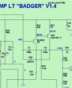
As far as I know the diode goes from the collector of the ksa1381 (q10) to the base
of the pre-driver Q9b. bridges C7 and 8 ...
OS
Attachments
The discussion began here. It seemed as though the nodes changed during the following posts. I never actually tried the fix on my HB. I am attaching the T-T schematic. You will see that the front end is very similar the to the HB.
Thanks, Terry
Thanks, Terry
Attachments
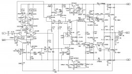
The discussion began here. It seemed as though the nodes changed during the following posts. I never actually tried the fix on my HB. I am attaching the T-T schematic. You will see that the front end is very similar the to the HB.
Thanks, Terry
I don't know about Q20 in the schema - it is a saturation clamp.
C5/6 are the TMC caps - reverse BAV21 across them. You should discuss
this w/dadod ???
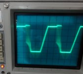
I KNOW it works on the Badger/wolverine (my sub amp has one) - little
saturation on clip.
OS
- Home
- Amplifiers
- Solid State
- diyAB Amp The "Honey Badger" build thread