Some Badger numbers
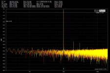
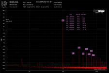
Dual mono Badger build... I decided to have a quick peak at some numbers. I love this amp, and when I took a quick look, this is what I saw.
Dual mono Badger build... I decided to have a quick peak at some numbers. I love this amp, and when I took a quick look, this is what I saw.
Attachments
Last edited:
Nice to see another person taking measurements.Dual mono Badger build... I decided to have a quick peak at some numbers. I love this amp, and when I took a quick look, this is what I saw.
Something is not right with your setup.
You plot should look more like this.
After years of testing this is the best wiring arrangement.
The load resistors are just temporarily mounted on that plate as I'm waiting for my heatsink to arrive.
Those are the best resistors to use as they are non inductive.
Send me a pm if you need anymore information.
Also check out this link
QA401 - Differential measurements with attenuation - QA401 - QuantAsylum Forum


What are you using for your board? I'm currently building a badger for my father, taking a break from tube amp stuff lol 🙂
it is a universal board that can take in 2 or 4 pin caps...
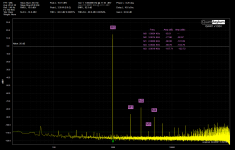
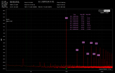
Okay folks, starting to get my head around the Quant. The cabling and noise floor stuff is a bit high as I haven't worried about it yet. I think the numbers look much better, but need some cleaner signals and and to attenuate.
Anyway, here's the screen grab... First ir right second is left. Looks like the supply on the left is making more noise... dunno why, but might look at it might not. 🙂
Anyway, here's the screen grab... First ir right second is left. Looks like the supply on the left is making more noise... dunno why, but might look at it might not. 🙂
Attachments
Last edited:
Starting to look better that's for sure.
Some other points.
Follow the manual for you setup and work out which output and input has the lowest noise.
One input and one output will be better than the other. Then setup to use that
Save a configuration file for 1k (996.0937) and 16k (15.98144)so you can get at least 6 harmonics out to 96k
I've found that the cleanest output level is -0.5dbv
Mute the other output.
Once you know the best output. Set the dc offset correctly to 0mv or as close as possible.
Then set your stop frequency to 96khz
You my need to enter 95.99999khz as there was a bug. Not sure if its fixed.
View attachment 954542
Last edited:

Always good to quote your loopback distortion at that frequency and input level.
For instance my loopback at 1khz and -5 dbv input voltage is 0.00043%.
And when I measure my HB it now measures the same after the mods I did. So the distortion at this point is not measurable.
I have purchased the bob Cordell distortion magnifier so I can actually measure it.
Just got to find the time to build it.
1k loop -.50db at Max input if +6dbV is 0.00092%
1k loop -.50db at Max input if +26dbV is 0.00048%
Left channel is the best on mine.
1k loop -.50db at Max input if +26dbV is 0.00048%
Left channel is the best on mine.
Last edited:
1k loop -.50db at Max input if +6dbV is 0.00092%
1k loop -.50db at Max input if +26dbV is 0.00048%
Left channel is the best on mine.
Left input or left output?
You can mix them. For example left output and right input.
A custom input attenuator helps you dial in the QA401 input voltage sweet spot.
I didn't go there, if I do you should be able to go to both + and - sides as well no? If so that makes for a lot of combos.
Not sure. Never tested that. I can't imagine that the outputs or inputs are floating. So I think that you would run into a grounding problem if you tried to run your output from a negative terminal reversed and then your input from a positive terminal...I didn't go there, if I do you should be able to go to both + and - sides as well no? If so that makes for a lot of combos.
Don't forget to set the DC offset. It's a bit of a pain as you need to adjust the number in the dialogue box. Then close it before the voltage changes. Then you need to open the dc offset dialogue box again and tweak the value again. Close it. Check it... etc over and over again until you reach 0mv
Last edited:
I see a function called output trim and I think this is what you are talking about. Dumb question, where is the DC offset display, or displayed as?
Yes output trim. You need to measure it with your multimeter. Adjust the number in the dialogue box up or down until your DMM reads 0mvI see a function called output trim and I think this is what you are talking about. Dumb question, where is the DC offset display, or displayed as?
I have it to 0-150uV from 3mV I could probably get it a little3 better, but wth. Out trim is -9400
Just get it as close as you can, I wouldn't worry about what value the Out trim becomes.I have it to 0-150uV from 3mV I could probably get it a little3 better, but wth. Out trim is -9400
Have you noticed any difference in your readings?
I hadn't ran any since the calibration, but your post got me out of bed to check it. I need to build an atten.
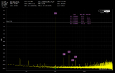
On the +6db level I can't get hardly anything without an input clip warning.
At 26db I can get to about -5.00 before it goes input clips at that I think I, seeing some distortion from being so close. I could look at it on the scope to see and might do some tomorrow.
On the +6db level I can't get hardly anything without an input clip warning.
At 26db I can get to about -5.00 before it goes input clips at that I think I, seeing some distortion from being so close. I could look at it on the scope to see and might do some tomorrow.
Attachments

Last edited:
I hadn't ran any since the calibration, but your post got me out of bed to check it. I need to build an atten.
On the +6db level I can't get hardly anything without an input clip warning.
At 26db I can get to about -5.00 before it goes input clips at that I think I, seeing some distortion from being so close. I could look at it on the scope to see and might do some tomorrow.
Here are my gerber files and calculation sheet
male connector
10X BNC male plug solder PCB mount RF coxial converter connector | eBay
female connector
WM5517-ND
other info should be here
QA401 - Differential measurements with attenuation - QA401 - QuantAsylum Forum
and I believe you have everything else
Attachments
Hmm, never ordered a board made before, the prices I'm seeing it's not going to happen. Anyone have a good cheap company?
JT
JT
- Home
- Amplifiers
- Solid State
- diyAB Amp The "Honey Badger" build thread