Hi Guy's,
Please use the Poll's below to indicate;
1. Your color preferences for both the EF3 and IPS boards.
Wolverine Project - Poll for PCB Color's
2. Your closest shipping location.
Wolverine Project - Poll for shipping location
This will help us start to get things organized.
Please use the Poll's below to indicate;
1. Your color preferences for both the EF3 and IPS boards.
Wolverine Project - Poll for PCB Color's
2. Your closest shipping location.
Wolverine Project - Poll for shipping location
This will help us start to get things organized.
I'm running a 5ch Honey Badger in one chassis. heatsink for each ch is a 4U300mm (internal). Bias is set to 70+mA pr outputpair (210+mA total), and +/-57Vdc rails. And that is plenty. So there should not be a problem running a 2ch with 3U400mm sinks for each ch. Actually i'm now in the process of building just that. A 2ch Honey Badger in a 3U400mm chassis.I built an integrated Gainclone amp for my parents to celebrate their 50th anniversary about 15 years ago and it's time I built something new for them. I've been considering various amplifier and preamp/buffer options for a while. The Wolverine is a very strong contender for the amplifier so long as the boards are made available sometime in the next 2-3 months. I'm happy to build on the bleeding edge but have a few questions for JT and the rest of the Wolverine design team:
- Is it reasonable to assume that Wolverine pcbs will be available in the February - March 2022 timeframe?
- Would a 3U Dissipante chassis from the store provide adequate heatsinking for the Wolverine?
- Do you foresee any issues with pairing a simple diamond buffer or a Wayne's Burning Amp 2018 line stage with the Wolverine design?
I'm not asking for guarantees; best guesses are fine.
Many thanks,
Scott
I'm clueless about electronics design/operation but I read the entire thread. Just want to say, the transparency, endless iterations over all details and, general commitment by the group responsible are exemplary.
For those like me who are very comfortable (and at least good enough) soldering, a detailed build guide and bom will be critical. Having said that, I've signed up for boards and will see what comes of it lol.
Anyway, just a big thanks and much respect to the design crew
For those like me who are very comfortable (and at least good enough) soldering, a detailed build guide and bom will be critical. Having said that, I've signed up for boards and will see what comes of it lol.
Anyway, just a big thanks and much respect to the design crew
Hi Guy's, Just a quick update.
The prototype 3 boards have arrived and Neil is underway with the board verification process.
The prototype 3 boards have arrived and Neil is underway with the board verification process.
Hi Guy’s.
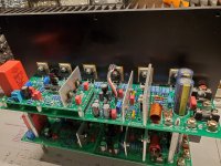
After some 9 months of development, I’m very happy to announce that the build and verification of the prototype 3 PCB was a success.
Neil kindly built the Prototype 3 for us and followed the build guide to the letter to ensure all the DiyAudio Members that build this amplifier have relevant & clear information on:
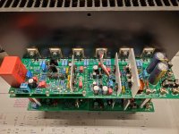
Please note that Prototype 3 is on top and Prototype 2 is on the bottom in the attached images.
I can also share some of our distortion measurements with you all.
These measurements were taken on prototype 2 using the QA-401 together with Bob Cordell’s distortion magnifier.
This particular build of prototype 2 did not used matched transistors.
1Khz, 80Wrms, 8 ohm load 0.00006%
10Khz, 80Wrms, 8 ohm load 0.00035%
Neil, has also told me that the amplifier went together effortlessly and just worked. This build provided the opportunity to test and edit the build guide for accuracy and it worked out extremely well. The guide was written to reflect a logical sequence of steps to make the build and power-up trouble free. We also included some technical detail that we thought would be helpful to the less experienced builders.
Although Pete Vogel (Ostripper, OS) was not part of our small team, his initial work and project goals helped to keep us all motivated and focused over the past 6 months.
I would like to make mention and thank the people on this team for all the unpaid time and effort they have put into this project. The names of the members are Keantoken, JJS (Jeremy), Harry3 (Harry), Neilshop (Neil), Johno (John), thompsontechs (Jim), Thimios (Thimios) & Brettn56 (Brett).
Without them this project would not have been completed, researched and tested to such a high standard.
We will spend a few more days verifying the board to ensure.
Please note.
You have all been so very patient and supportive as this development process has taken place.
I wish you all a happy new year and we will update you all once the final boards are ready to order.
Enjoy the images of the Wolverine IPS and the Precision EF3 Board.
After some 9 months of development, I’m very happy to announce that the build and verification of the prototype 3 PCB was a success.
Neil kindly built the Prototype 3 for us and followed the build guide to the letter to ensure all the DiyAudio Members that build this amplifier have relevant & clear information on:
- What to consider prior to building this amplifier.
- How to build this amplifier.
- How to setup & test this amplifier.
Please note that Prototype 3 is on top and Prototype 2 is on the bottom in the attached images.
I can also share some of our distortion measurements with you all.
These measurements were taken on prototype 2 using the QA-401 together with Bob Cordell’s distortion magnifier.
This particular build of prototype 2 did not used matched transistors.
1Khz, 80Wrms, 8 ohm load 0.00006%
10Khz, 80Wrms, 8 ohm load 0.00035%
Neil, has also told me that the amplifier went together effortlessly and just worked. This build provided the opportunity to test and edit the build guide for accuracy and it worked out extremely well. The guide was written to reflect a logical sequence of steps to make the build and power-up trouble free. We also included some technical detail that we thought would be helpful to the less experienced builders.
Although Pete Vogel (Ostripper, OS) was not part of our small team, his initial work and project goals helped to keep us all motivated and focused over the past 6 months.
I would like to make mention and thank the people on this team for all the unpaid time and effort they have put into this project. The names of the members are Keantoken, JJS (Jeremy), Harry3 (Harry), Neilshop (Neil), Johno (John), thompsontechs (Jim), Thimios (Thimios) & Brettn56 (Brett).
Without them this project would not have been completed, researched and tested to such a high standard.
We will spend a few more days verifying the board to ensure.
- All the data we collected during the testing of prototype 2 checks out.
- Photos and any additions details are added to the BOM and build guide.
- Any minor tweaks to the pcb’s have been completed.
Please note.
- We will not be posting Gerber's of the PCB’s, so please don’t ask.
- Initially we will only send out a BOM, Build Guide & Schematic to people who pay for their boards. This is due to the parts shortages at the moment. We want to give those members who do pay every chance to order the parts from the BOM.
- Once a few months have passed we will post the BOM, Build Guide & Schematic online for members who would like to refer to them in future.
You have all been so very patient and supportive as this development process has taken place.
I wish you all a happy new year and we will update you all once the final boards are ready to order.
Enjoy the images of the Wolverine IPS and the Precision EF3 Board.
Attachments

Congratulations to all the staff! You did an amazing work! Comparing to this, the HB seems a children toy...
Gaetano.
Gaetano.
Thank you everyone that has worked on this amplifier,
Looking forward to making this one.
Big thanks to Stuart for helping learn what I need to know about this amplifier style
Looking forward to making this one.
Big thanks to Stuart for helping learn what I need to know about this amplifier style
Congrats! Amazing to be able to follow all the work that has gone into this, I've been eagerly watching since about the third post. This is the most excited I've been to start building 🙂
Congratulations to the entire team! This is a very exciting moment for those of us in the wings -- I can't wait to get started!
It is good to see this design is still inching toward final design.
The Slewmaster I built early 2017 is still working flawlessly.
Since the Wolverine is essentially a refined version of the Slewmaster, I doubt the new Wolverine would be any different.
The Slewmaster I built early 2017 is still working flawlessly.
Since the Wolverine is essentially a refined version of the Slewmaster, I doubt the new Wolverine would be any different.
Excellent work. I hope to order this board when it makes it to the DIYAUDIO store (or perhaps earlier if there are extras). I wish the early adopters the best of luck with their builds...
Best,
Anand.
Best,
Anand.
So there should not be a problem running a 2ch with 3U400mm sinks for each ch.
AudioSan:
Sorry for the belated response -- I missed your post and was distracted over the holidays. This is great news!
Many thanks,
Scott
Approx 80mm x 260mm with mounting holes to the UMS specification for the Precision EF3 board and the Wolverine Input board is approx 50mm x 120mm. The Wolverine is plugable and mounts on top of the EF3 (with only a ground plane underneath). This design allows the alternate Spooky input scheme to be plugged in if and when it becomes available.
Well done guys the results look good, what does the final schematic look like if it is to be public ?
-Dan
-Dan
Hi Dan, your question is answered at points 2,3 in post #1406Well done guys the results look good, what does the final schematic look like if it is to be public ?
-Dan
Last edited:
- Home
- Amplifiers
- Solid State
- DIYA store "Wolverine" (Son of Badger) .... suggestions ??