OS you don't like this suggestion?
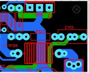
Also I cannot tell what the lead pitch is for C113. Can you make it variable like R127, that it's connected to? My preference is to use a large plastic cap at the output in case of oscillation etc?
Thanks for another wonderful design.
C113 - is now 5/7.5/12mm LS. What LS were you looking for ??
OS
Attachments
I did say Q201, 202 ( a series pass regulator for the DC servo) not Q101,102 ( a ripple eater or C multiplier)Why would you ask me this ??
I see ~60V-12V across Q201,202 C-E and the bias current of the U1(TL071 DC servo) is 2.5mA max, so I calc 0.12W, looks okay, just looked suspicious, sorry to question your design 🙂
No problem , I'm using a LT1029 (similar low power to LF411). It just
uses under .5ma per rail.
The ripple eaters will possibly be powering more current hungry IPS's.
The original spooky and my greenamp use 25mA per rail. Still , TO126
can take that. TTC/A004 is 6-7W at 40C.
So, after using hot zeners in these designs .... why not lighten the load
with my 12v supplies. With the EF3 , why not aim to create >15ma IPS's
that are just big op-amps. My "greenamp" uses just 11mA per rail.
As a design change , I could most likely run the pass zeners at .5mA with
no penalty.
OS
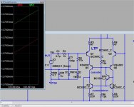
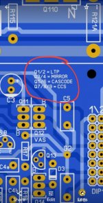
I liked it a lot. The helper tightened up the mirror from mV to uV/uA-nA. But , not much
in the way of THD/offset improvement.
Agreed, there maybe not much of an improvement in the simulator when all the transistors characteristics are the same. But please consider the real world were there devices won't match as closely.
You said that you are going all out on the amplifier OS. Please reconsider adding the helper transistor.

OK , I'm clearing out room on the layout.
First , where to reference the helper. You say ground... I say the hell with
ground. (below)
We are just beta enhancing the CM , right ?
It seems to work really good. Either ground or the cascode divider reference are dead
even at 15nA difference.
My previous 6ppm went down to 5.47.
Sheeeet , have to re-lable everything from Q5 up.
PS - ground reference would of required a high Vce device. Screw ground.
OS
Attachments
Last edited:
C113 - is now 5/7.5/12mm LS. What LS were you looking for ??
OS
Perfect - thanks.
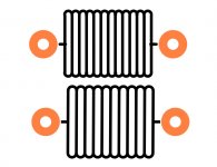
mpc74 is 14mm @ +/- 1mm tolerance. So,13-15mm. My Re's are 16mm with
1mm holes. Should fit nice.
OS
1mm holes. Should fit nice.
OS
PS - ground reference would of required a high Vce device. Screw ground.
OS
Thanks OS, and thank you for thinking about the implementation of this CM helper so elegantly.
What's you've come up with is awesome.
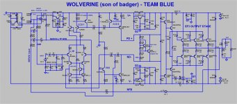
Small tweek to the silkscreen and can you add the IPS Quesent current to the schematic.
View attachment 939731View attachment 939732
View attachment 939731View attachment 939732
Attachments
Last edited:
Forgot the little educational part there - updated.
A just noticed the helper tames LF THD better. I'm getting .0015% 4R 15-25hz.
The helper absolutely "forces" input pair current symmetry. Uses just a few
uA to do so.
This level of subsonic performance is what Elliot sound (ESP) warned would be
degraded by a servo. Phase shift in what little NFB "bleeds" past the Servo
integrator does this - degenerative FB 🙁 .
Looks like the helper is negating some of that -90db (yes, its that low at 20hz) garbage
creeping past the filter. cool !!
Oh , cool drops off to 3ppm at 10 hZ , jumps back to 15ppm at 15hZ. I saw this
in my AC analysis ,10HZ is where the integrator's phase shifts.
So this amp is >15ppm 10hZ - 1Khz ... better at 1k -20KhZ (5-6ppm)
Plenty of margin with 100/470pF (C4a/b).
OS
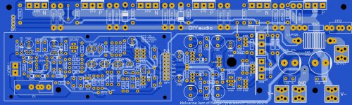
I will try to see if a home made pcb is possible...
Difficult but not impossible.
What is the pcb dimmentions?
Difficult but not impossible.
What is the pcb dimmentions?
Last edited:
Now I do.
Still only 16 thread option. I have a 36 thread Xeon V3.
Seems faster. Infinite pen thickness.
Ohhh , I can get rid of that dark blue stupid plot color.
Nice!!
OS
Still only 16 thread option. I have a 36 thread Xeon V3.
Seems faster. Infinite pen thickness.
Ohhh , I can get rid of that dark blue stupid plot color.
Nice!!
OS
I will try to see if a home made pcb is possible...
Difficult but not impossible.
What is the pcb dimmentions?
253mm X 76mm - store standard.
OS
C113 - is now 5/7.5/12mm LS. What LS were you looking for ??
OS
At 12mm C113 might be to close to edge for PCB production.
There are alot of 10mm Polypropylene and Polyester caps at 100nf.
So maybe max it at 10mm not 12mm?
At 12mm C113 might be to close to edge for PCB production.
Maybe C113 can be rotated 90 degrees counter-clockwise.
- Home
- Amplifiers
- Solid State
- DIYA store "Wolverine" (Son of Badger) .... suggestions ??