Superdave
For your reflector I would suggest useing fiberglass you can pick up fiber glass cloth and resin at your local auto parts sotre or hardware store it is nice cuz it will withstand very high temps and as with the chrome paint I painted a computer case touched it 3 days later and it left a permant finger print. So I got 1000 grit wet sanding paper and tryed to polish it and ended up with an ugly dull grey case :/ I was very sad. chrome plating would be the best route I think. BTW how do you find the curve for the reflector I was wanting to build one but Im not sure how to make one that would work right.
Darth
Well I got a white king size sheet cut to about 9 feet wide and 7 feet tall with a 640X480 LCD panel I fill the whole screen and watch DVDs and the only thing I see wrong is the brightness hopefully Ill fix that soon with the new screen Im building other than that the picture looks awsome if I could find a good bulb that would last more than 750 hours Id make this my dedicated tv but for now its just for movies and games. If you wanna come to Ft worth and see first hand then come right over and Ill pop in a dvd.
Tech head,
No they dont use brute force, they use advanced technology which is what you pay for in a manufactured projector. Most of the projectors I have seen use a high intensity discharge lamp with a arc size of under 3 mm. You all know lamps like this are very exensive. There is always a reflector on the lamp mostly an elliptical to take the light down to a small spot size. Light from the lamp assembly has uneven illumination and shadowing caused by reflector imperfections and the body of the lamp. This uneven light is made to be even by various techniques but commonly by passing the light into one end of a glass rod. Light coming from the other end of the glass rod is now even over its area. The light is expanded out into a parallel beam and either used directly (older method) or split into P and S polarisation and the unused polarisation part is changed in polarisation and added to the first part so the total energy of the lamp is used rather than half being wasted. The light is split into red green and blue components. Then on to the lcd units usually three monochrome panels all the same which means each panel only has one controlling transistor instead of three for a colour panel so they get economy of scale by making a lot of similar panels and since the transistors are smaller for monochrome they pass more light. Many manufacturers now use lcd panels with microlenses in front of each pixel on the front of the panels to assist in using the light passing through to its best advantage and increase contrast ratio. These three panels have to fitted with extremely good alignment so your red blue and green light all ends up at the same place on the viewing screen. One very important consideration is because the lcd panels are small around an inch square the optics have to be of exceptional quality otherwise when the small one inch square pictures are magnified to a large screen size the slightest imperfection would be very obvious. So you can see there is a lot of advanced technology going on turning out a stunningly brilliant picture in a small lightweight box. It adds up to many $$$$$.
Those who prefer to knock other peoples efforts and say what you are doing is a waste of time and money could easily change their stance and instead offer helpful suggestions. For example someone said the light has to pass through the lcd panel at 90 degrees. Fine. That makes sense but why stop there. How about researching larger size lens. Are they prohibitively expensive. What about plastic lenses. Could they do the job and how much cost. One interesting patent on the US patent data base #6377406 from Fresnel Optics Co suggested two things. First only supply polarised light to your lcd because that will stop the lcd heating up and increase contrast, and secondly use one fresnel before the lcd as is usual with OHP and one fresnel after the panel to converge the image to your projection lens. This company claimed by using good quality fresnels and adjusting them in a particular way you get a good picture. Other patents viz 5940149, 5900973,5898521 also deal with polarised light . These could be in the catagory of more advanced features and my starting point will be to take my LCD projection panel down to a lighting shop and tell them I want an OHP that will project this panel. Its all self contained and shows an opening screen when plugged in so its not a big deal. Then I can find out what lumen ohp's look promising then find out whats inside them and either buy one or duplicate it. I know very well that a 10 year old LCD projection panel will be well short of a modern projector but I dont care. There is no fun in going down the road and buying a projector and they are too expensive.
Marklar...this has been posted a couple times I think but we are now getting a bunch of message daily so I will just post it again..no biggy.
http://www.gwidijanto.fcpages.com/reflector.htm
Place the center of your light fillement at f1 and you want projecting lens at f2. This approach requires no fresnel, but requires a precise reflector and precise light & lens placement.
I am building this but I am only worried with the first have of the ellipse. I plan on having my light at f1 but I will put my fresnel at the equivilant center of the ellipse. This will gather all the light that is heading that direction but not necessarily right on focus. I am doing this because I doubt I can build a reflector and place my bulb(which has a large filliment anyways) in the exact spot. By using the fresnel (which is a lot better focusser than I can build) I should get A LOT more light projected straight through my LCD and into the projection lens.
Also...I was sitting at my desk thinking about fiberglass earlier and I had 2 images in my mind... The first is when I was 6 and I helped my dad fiberglass our boat. the fiberglass was quite rough and I feel the resin would stick to my mold. I want to be able to have a mold to create multiple reflectors. If you know how to make it not stick please let me know. Secondly I think of car body kits. This is really the feel I would like. They are light...I can paint and sand them smooth to eventually electroplate...are these car parts made out of the same stuff I would have used on my dads boat??
My biggest concern with fiberglass is the resin sticking to the mold. That is why I was thinking there is some way to get pour plastic over it and just let it cool or dry and just pull it off. Sorry for the rambling about fiberglass and plastic...but it if for the purpose of building reflectors.
Thanks,
Dave
Darth
The cold cathode piece is nothing but waste of money. Some expert suggested it earlier on this thread and as far as I am concerned it was an absolute waste of my hard earned money.
The cold cathode piece is nothing but waste of money. Some expert suggested it earlier on this thread and as far as I am concerned it was an absolute waste of my hard earned money.
Darth, your statement of the LCD to be a lens isn't true. Look through a panel projection panel watching environment. What you can see, all is much dimmer but there is no refractive element in the layers. Of course there is much filter effect ,absorbtion and scattering light, but no refraction that we know from optical lenses !
And another point: LCD-Panels+OHPs was a common setup for presentations in the 90s, which give fairly good results with OHPs upwards the 6000 lumens region. I have an 1024x768 panel. 16,7 mil. colors, OHp, 5200 lumen and have a good image. Ok, not comparable with the latest high end projectors, but i enjoy looking all kind of TV movie stuff for three months now! All in all, 500$. And the bulbs are cheap.(halogen 400w, 7$).
The problem for most DIYers seems to be, there's no real market for these specialized components, so a lot these guys go the trial and error route with ANY stuff.
I think you are right, if you mean the joy of making something is bigger than the knowledge, but this have to be paid with disapointment or even damage, at least with real money !
A did a lot of research on patent databases over projectors and didn't find the ultimative solution for better lighing efficiency.
I saw designs about lamps, which where completely disclosed with hybrid reflectors to gather all the light, which is coming out through a little aperture. But for DIY it's hardly makable, i think.
xblocker
Answers
Well I have stirred a real hornets nest havent I??
To answer many of the questions I have been asked.
Resolution = TV grade at the moment, but yes I could use a computer CRT to get better res. I was mainly after big screen DVD not PC but the concept is the same. Only probelm maybe to scan rate.
Servos = actually are realy high freq voice coils, less the speaker dome, I have mounted a small mirror at 45 degrees. The mirrors are mounted quite close to the output from the prisum so minimal deflection is required. I did have problems with the flyback (end of line return scan). This was over come by making the flyback
voltage greater to move the coil more rapidly.
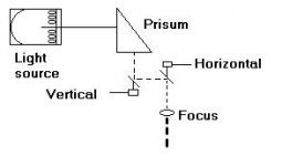
Layout, oftheend was mostly correct. In the three tubes is a pack of LED's (one colour only per tube) in the centre on the pack is a fibre optic lead. At the other end of the tube is a concaved mirror that focuses the light into the fibre. The output of each of the fibres is placed into a prisum at the appropreate spectral points. The prisum then combines (mixes) the three colours into one light beam. This is feed to the Horizontal deflection servo mirror, then onto the vertical servo mirror. This then goes out through an old projector mirror that refocuses the light beam, so as to fatten the beam to allow it to fill in the gaps between lines in the picture.
The LED packs have their DC supply modulated by the respective RGB output from the TV chassis. As well as the Horizontal and vertical servos from the Yoke (deflection) output IC via a resistor network to lower the levels for the voice coils.
Note that the servo mirrors have to be close to the prisum so as minimal movement causes maximum deflection. For PAL (NZ TV standard) horizontal freq = 15625Hz and Vertical is 50Hz easy for a voice coil to produce. If you do not move the coil by much the deflcetion becomes more linear which is required above all else.
The idea of the Lasers instead of the LEDS is to reduce space and increase light output. Theory says I should be able to produce an image upto 200m away or upto 60' x 40'. A little large for my lounge.
Engineer = Yes, specalising in High power broadcast systems etc.
Does this help??
😕
Well I have stirred a real hornets nest havent I??
To answer many of the questions I have been asked.
Resolution = TV grade at the moment, but yes I could use a computer CRT to get better res. I was mainly after big screen DVD not PC but the concept is the same. Only probelm maybe to scan rate.
Servos = actually are realy high freq voice coils, less the speaker dome, I have mounted a small mirror at 45 degrees. The mirrors are mounted quite close to the output from the prisum so minimal deflection is required. I did have problems with the flyback (end of line return scan). This was over come by making the flyback
voltage greater to move the coil more rapidly.
Layout, oftheend was mostly correct. In the three tubes is a pack of LED's (one colour only per tube) in the centre on the pack is a fibre optic lead. At the other end of the tube is a concaved mirror that focuses the light into the fibre. The output of each of the fibres is placed into a prisum at the appropreate spectral points. The prisum then combines (mixes) the three colours into one light beam. This is feed to the Horizontal deflection servo mirror, then onto the vertical servo mirror. This then goes out through an old projector mirror that refocuses the light beam, so as to fatten the beam to allow it to fill in the gaps between lines in the picture.
The LED packs have their DC supply modulated by the respective RGB output from the TV chassis. As well as the Horizontal and vertical servos from the Yoke (deflection) output IC via a resistor network to lower the levels for the voice coils.
Note that the servo mirrors have to be close to the prisum so as minimal movement causes maximum deflection. For PAL (NZ TV standard) horizontal freq = 15625Hz and Vertical is 50Hz easy for a voice coil to produce. If you do not move the coil by much the deflcetion becomes more linear which is required above all else.
The idea of the Lasers instead of the LEDS is to reduce space and increase light output. Theory says I should be able to produce an image upto 200m away or upto 60' x 40'. A little large for my lounge.
Engineer = Yes, specalising in High power broadcast systems etc.
Does this help??
😕
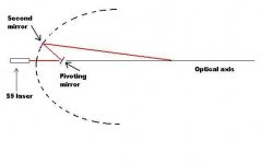
For designing reflectors this might be helpful. Use a cheap laser onto pivoting mirror. As you move the pivoting mirror the laser will simulate light rays coming from your bulb. The second mirror reflects the light rays to where you want them either straight out (parabolic reflector ) or down to the second focus point (elliptical). Both mirrors about 1/2 inch square. Pivoting mirror stays at the pivot position and just turns. Second mirror Mount on edge of piece of wood so it stays upright. When you have the simulated light beam going where its supposed to, mark edge of second mirror. Big advantage is you can see where the beams of light go to.
Attachments
mountain_nz, could you make little drawing of the lightpath of a single color unit ? What kind of fiber optics would you use ? I suppose this led package will behave like an extended light source.
How to focus these LEDs into the fiber without running into the same problems as with large filaments. And: inputting + outputting LED light is different from laserlight due to their different properties!
Main question: how to speed up and syncronize the prisms to the horizontal frequency? Look at laserprojector thread !
xblocker
re xblocker
The concave mirror in the stainless tube is moveable this then moves it focus point into the fibre, the fibre used was a bit of junk plastic fibre about 1.5mm thick. Losses are to bad over the short distance. Stainless tube is used so as to not waste any light.
Syncronising the scan rate is easy as the TV chassis has already done that for you. If you use spinning mirrors it would be bloody hard to say the least as the motor speed would only need to vary by 1 RPM and the picture would start to scroll horriably.
As the mirrors are mounted onto a voice coil and the physical movement is kept low the movement lineraity is kept. The main problem I had from the start was the flyback scan from the end of the video line to the start of the next line, this was overcome by amplifing the flyback pule to a point were the coil would react quick enough. My next idea to overcome this is to put the coil in a automatic gain loop, like a servo, this would be able to measure the movement of the voice coil and then make it move even more linear and return more quickly and to the optimum start point.
The point of using lasers is to remove the bulk of the LED tubes and the loss of the fibre cable.
Some one quized about greater resolution, I am still yet to get time to play with an impoved model, but it should be feazable if the CRT chassis will allow it if you go to 2048 Horz at a 75hz refresh non iterlaced would be a horz freq of 153600hz which is high but again you could now go to a peizeo transducer which will run above this even.
Another question was the maximum modulated freq of a LED well this is limited by the amplifier really as a LED can be turned ON and OFF at about 50Mhz, as we are only turning it OFF during the flyback and the start/end of feild points this will be well within the LED's limits.
here is a simple outline of the design, I am a work at the moment so it makes it a bit hard to keep answering this forum. Bear (BEER??) with me.
🙂
Attachments
Superdave
Fiber glass can be sanded smooth if you worked on a baot you prolly used the fiber powder it makes for a very smooth finish as for getting stuck to the mold im not sure if the resin will stick to it but i guess you could get some of that non stick spray you put in a frying pan or just rub some oil or grease on the mold that shouldn't effect the cureing of the resin
Fiber glass can be sanded smooth if you worked on a baot you prolly used the fiber powder it makes for a very smooth finish as for getting stuck to the mold im not sure if the resin will stick to it but i guess you could get some of that non stick spray you put in a frying pan or just rub some oil or grease on the mold that shouldn't effect the cureing of the resin
SuperDave: i was seriously considering getting nickle plated electroforms made, then plating them with a cold-mirror reflective coating. that would've been so sweet. but i think i'd have to contract someone out for it. is there any way to do DIY electroforming?
marklar: fiberglass would be really nice. any suggestions for getting the reflectance you need?
darth willis: most of the light being focused in the center problems originate from the use of the fresnel. switching to a light gathering method which is uniform fixes all problems. ellipsoidal, if deep enough, is nearly ideal.
myren
xblocker
think of an lcd or any peice of glass as a plano-plano lens and any thing that light (even air and the water inthe air) acts as a lens
mountain
just how many led's are in your machine? i dont pretend to understand how your setup is made but your pic looks like 1 led to one color pixel mabe if someone else explained it in laymans terms? please
Yeah!! Got my 250 watt MH today. I am testing the fixture right now, on the floor. It is a bright sunny day outside, but when i turn this thing on, it flushes all the daylight out of my room. It is brighter than the amount of daylight coming into my house, and i have a lot of windows. The color of the light is ever so slightly more yellow than daylight, nearer the color of the halogen worklight I was using. The halogen light rendered the colors on my panel perfectly, So I am sure that once i rework my box to accomadate this lamp, I will be styling. Sorry, no real useful info yet, but i am excited. I will share when Tests are done!!.
ok sutpid question some professinal projestors have a functioin so that when you place the projector below or above the center of the image is still square how do you compensate for this?
Myren...I know that DIY electroplating is fairly simple...I forget what liquid you use but you give one object a + charge from a battery and another object (I also forget if you object or metal source get then + or - charge) and place in a bath of the solution. Let it sit and voila....It's supposed to be quite simple (like a 6th grade science experiment).
As far as electroforming goes...I think it is VERY close to the same process...only instead of a thin film covering the object you get a thicker metal layer that you can remove. I really didnt think about this because I figured if I could just form plastic (or fiberglass) reflectors and electroplate (which I know I can do on my balcony) the reflectors would be quite lite. A reflector made from electroforming is actually solid metal (if I'm not mistaken).
I found this link when looking for a DIY electroforming site...although it doesnt supply DIY info it does explain it a little and DAMN they are producing EXACTLY what I want...At least it sounds like we are on the right track. Take a look at those reflectors... almost exactly the size and shape I plan on making...
http://www.optiforms.com/what.htm
I'm getting all excited again.
Later,
Dave
Keystone correction
Tomithy - I think what you're referring to is when the projector is placed at an angle to the projecting surface. This produces an image which isn't square on the wall. It is in fact the shape of a keystone, which is the name of the top stone in a brick archway.
Anyway, to overcome this, the image which is being projected has to be altered to compensate for the keystone shape on the wall. Imagine the image projected is wider at the top than at the bottom. To compensate for this you have to change the image on your LCD or whatever to have a wider bottom than top, do you see what I mean?
This is a bit difficult on LCDs or DLPs because they are of fixed resolution, and you end up with a final image which suffers from the same problems as when you try to stick a 1024x768 image on an 800x600 LCD by squashing it. I think you get the picture.
On CRTs they have no pixels, so the problem wouldn't be so apparent.
Screen material
Superdave; Myren's going to go nutz when he sees that!
A link for paint-on screen material -
http://www.goosystems.com/
Superdave; Myren's going to go nutz when he sees that!
A link for paint-on screen material -
http://www.goosystems.com/
Keystone:
Theoretically you could tip the lcd a bit. You would most certainly lose a little brightness, and i would say tipping it more than 5-10 degrees in any direction would have a significant impact on the image quality, ie. uniformity of brightness. You might compensate with a change in the position of the reflector, but in any case i think you would lose brightness.
My first test with the new 250 MH is done... I am very happy to report that the image is MUCH brighter. I tested during daylight, and the image produced was near as bright as the image produced by the 175 MV in darkness, and the colors are much, much better. (i can see red again!!) This test is using my old reflector, the coffee can parabola. I have a new reflector built out of aluminum roof flashing, I just have to fit it inside the case and cut around the bulb. I was just eager to test. So, at the moment, the light leakage is incredible, The area of the projector was lit brighter than ambient daylight during my test. I am willing to bet that once I contain the light, add polarizers, and either paint my dark grey wall or make a screen, that this image will be watchable in ambient daylight. It is near so now. Directing all the light to the lcd should increase brightness ~25%. (this is estimated by simply covering the open top with a blanket, a no-no as far as fire concerns go.) According to the info on polarizing recycling, a good setup can yield a 45% increase in brightness overall. I cannot wait until i test at nightfall.
There exist 2 types of keystone correction.
The first what scot_lad described is the digital correction. The second is the optical keystone correction, which comes from photographic techniques.
Here comes the Schleimpflug condition into the game. Scheimpflug discovered some laws concerning Off-axis imaging, which is also usable for projecting. He statet, if the object-plane, the lens-plane and the image-plane are meeting in one point, then you have a sharp image.
Optical keystone correction cannot only be done with LCD PJs, also many high end OHPs have it. Digital correction alone can only correct the trapezoid image in off axis projection, but cannot sharp the image.
xblocker
- Status
- Not open for further replies.
- Home
- General Interest
- Everything Else
- The Moving Image
- DIY Projectors
- DIY Video Projector