When I was a kid, my father had a Volkswagen with a Bendix "Sapphire" radio in it. To my ears, it sounded better than the other AM radios I was listening to at the time. I used to deliberately tune the station off center to get a little more treble, while sitting in the car parked in our driveway.
I always wondered why that radio sounded better. The day came when I had the opportunity to take it apart and noticed it had 255kHz IF transformers. "That must be the reason", I dreamed.
Fast forward 48 years and now I read "The lower frequency will tend to have a narrower bandwidth thus chopping off more of the high frequency information..." Of course! Dead wrong in my thinking, but at least I was and still am, interested ;')
Lower IF transformers tend to be narrow in bandwidth, this gives also more gain from IF tube.
4.5MHz was the sound if in B&W TV's here in Argentina, I remember the 6BN6' s high Q limiter coil, tuned with only 15pF, And I used them in my first 3.5MHz receiver (80mts band ham radio), with a little more capacitance.
4.5MHz was the sound if in B&W TV's here in Argentina, I remember the 6BN6' s high Q limiter coil, tuned with only 15pF, And I used them in my first 3.5MHz receiver (80mts band ham radio), with a little more capacitance.
When I was young all of these kind of parts were freely available since discarded tube TV's, radios, and HiFi sets were common. Now they are all surface mounted parts with "integrated selectivity." Modern TV's and radios contain very few wound coils.
Somewhere in my distant past there was a two or three month running article in one of the major US electronics publications that featured a build up of a HiFi tuner. It would have to been published in the early to mid 60's for it to have been tube based.
Somewhere in my distant past there was a two or three month running article in one of the major US electronics publications that featured a build up of a HiFi tuner. It would have to been published in the early to mid 60's for it to have been tube based.
Wow.
That is some super impressive DIY.
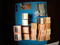
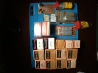
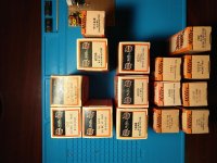
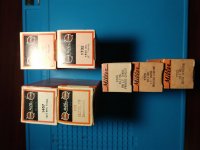
I'll dig out the other sacks of transformers this evening and see just what is there.
That is some super impressive DIY.
I'll dig out the other sacks of transformers this evening and see just what is there.

Tons of 262 and 455 KHz.
Several sets of 4.5 MHz.
Not as many 10.7 MHz as I thought, unfortunately.
I pulled all the transistor parts, there are some of those, also.
I only have a dollar each in them, so it's like dollar daze for transformers ...
Several sets of 4.5 MHz.
Not as many 10.7 MHz as I thought, unfortunately.
I pulled all the transistor parts, there are some of those, also.
I only have a dollar each in them, so it's like dollar daze for transformers ...
Attachments
Hi guys
you are courageous to try to build an FM radio with tubes today considering how hard some parts will be to source, but very interesting. Highly recommend you steel from old units what you need.
As usual, there are Chinese made options on ebay if you want to maybe start with and modify. I'm not advertising just sharing.
Audiophiler Vacuum Tube FM Radio Vintage HiFi Audio Stereo Receiver DIY Kit | eBay
Vintage Vacuum Tube FM Radio Wireless Audio HiFi Stereo Receiver Board DIY Kit | eBay
Can't find it but I recall seeing the seller had a finished unit with metal case and frequency display as well.
My approach would be to
Maybe build in in progressive steps replacing more and more circuit sections of an working FM stereo unit with your DIY tube based sections. Example replace the chip based MPX and output section first, then the IF section, then the RF section. This way you have a working unit each step of the way and only the new section you added requires to be troubleshooted if suddenly you don't get reception output. The dial and pointer and string I strongly recommend you take from an existing working unit as is. and build inside that donator box. Then you can add signal strength and center tune indicator tubes as a nice to have. 🙂
Keep us informed love to read and see pictures of your work.
/Paba
Last edited:
Take a look at High (Audio) Quality AM Tuner - diyAudio.Keep us informed love to read and see pictures of your work. /Paba
Cheers.
Hi Paba,
both kits you've suggested apear to be the same.
It's hard to believe that proper alignment is manageable without suitable equipment (sweep signal generator, o'scope). Look at those lose ferrite IF filter cores. Hence I'd fear great disappointment on the outcome.
Best regards!
both kits you've suggested apear to be the same.
It's hard to believe that proper alignment is manageable without suitable equipment (sweep signal generator, o'scope). Look at those lose ferrite IF filter cores. Hence I'd fear great disappointment on the outcome.
Best regards!
I don't read German but those pictures make me visualize a possible diy radio project for a completely noob like me. So, hoping that I'm not disturbing, I need to ask if something like this ukw tuner rohren | eBay advertised as "working when pulled" could be enough for a first listening or additional modules are needed to deliver sound?
From these offers I'd chose a FM frontend from an old Telefunken, Saba, Grundig etc. radio and add an IF strip/ratio detector. Don't take a »Nachrüstsatz«! These are complete with AF output, but often much inferior to a superheterodyne. But there are exceptions as well, as the Saba UKW S III or UKW S IV units, which are complete superhets with two IF stages.
Best regards!
Best regards!
...and also for old b/w and PAL colour tv's here in Europe...
Best regards!
Actually the distance between sound and picture carrier was 5.5 MHz rather than 4.5 MHz down here, and I think 6 MHz in the UK. Later stereo TVs had a second sound carrier at 5.74 MHz from the picture carrier (no idea what was used in the UK). The (suppressed) colour subcarrier was at 4.43361875 MHz offset in the PAL system.
From these offers I'd chose a FM frontend from an old Telefunken, Saba, Grundig etc. radio and add an IF strip/ratio detector. Don't take a »Nachrüstsatz«! These are complete with AF output, but often much inferior to a superheterodyne. But there are exceptions as well, as the Saba UKW S III or UKW S IV units, which are complete superhets with two IF stages.
Best regards!
Many thanks for the suggestions! Looks very interesting. I'd like to give it a try.
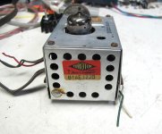
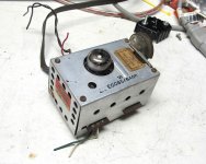
Guess what I found:I do have a thought - perhaps you can locate some of the old Danish (?) tube based Torotor FM tuner modules and restore them - making them the basis of your project. These were commonly used in Eico tuners, and I suspect several 60s era European manufacturers used them as well. They inlcluded various IF strips and front ends and were pcb based.
Attachments

I used toko 10k coils which can withstand 100v and put them back to back to form the double coupled tuned circuits for the IF. The small footprint prevents coupling between the IF stages.
.png")
With such a tuner I built my 1st FM radio. With two IF stages, last one limiter, dual diode for demodulation and a magic eye. No equipment available to measure sensitivity or AM rejection. The sound was great, 20 Hz to 20k as transmitters were mono. Experimenting, I soon discovered that 3 IF stages couldn't be useful AND stable on the relatively small chassis. That was the start to dual conversion and results were better, especially suppression of impulse noise interference (no spark "taming" back then).Guess what I found:
- Home
- Amplifiers
- Tubes / Valves
- DIY valve radio