The R390 was in the US Navy electronics equipment phase of 'A' school.
The instructors would put problems in receivers and transmitters.
The very first steps of troubleshooting them was to check all the functions without getting inside the unit; find the symptom first. I checked their "busted" R390 and declared there was no trouble. They asked me to check it again. I said whatever you broke, it is now working. They said, right.
That was a very important lesson about "broken" equipment I would have to 'fix' on the destroyer I was on for 2 years (including R390 receivers).
Re-wiring the transmitter antenna tuner multi pin control connector in the dead of night, and with a blanket over our heads (darken ship conditions in the Gulf of Tonkin), was not a fun task.
The R1050 was an all solid state HF receiver, except for the dual tube preamp at the RF input (to protect the solid state circuitry).
Last edited:
Dave's Homemade Tube Radios
Try looking up diy 2 tube regenerative radio. Lots of results but they seem to
be only AM and short wave not FM which is not really what you want 🙁
But they look like cool projects.
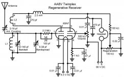
Here is my favourite, he explains each part of the circuit and how to build it.
The AA8V Twinplex Regenerative Receiver - Schematic Diagrams and Circuit
Descriptions
Try looking up diy 2 tube regenerative radio. Lots of results but they seem to
be only AM and short wave not FM which is not really what you want 🙁
But they look like cool projects.
Here is my favourite, he explains each part of the circuit and how to build it.
The AA8V Twinplex Regenerative Receiver - Schematic Diagrams and Circuit
Descriptions
Attachments
Oh, AM tuners, specially something as crude as a super regenerative one, CAN receive FM very well, by using "slope detection", you tune receiver slightly to one side of frequency of interest.
My first experiments on FM receiving (starving student in the late 60´s) were based on a home built superreggy, go figure.
My first experiments on FM receiving (starving student in the late 60´s) were based on a home built superreggy, go figure.
Regenerative receivers have better audio quality because of less stages distorting the signal. I have a couple of them.
Attachments

Last edited:
I have tried a couple of super regenerative RX for FM. They are sensitive but however they rely on slope detection of the FM, and hence did not give good results for me.
One suggestion you could try is to go with a modern FM front end bought in with semiconductors, and do the IF strip - FM detector with valves. You could still use ceramic filters.
Could be easier but maybe not what you want. Interesting...
https://www.vintage-radio.net/forum/attachment.php?attachmentid=78186&d=1365088013
Last edited:
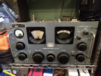
6A3Summer, did you have any of these R-274/C ( SP-600 ) on the ship? It has a ganged tuning capacitor that runs almost the depth of the radio, making it much more of a band cruiser than the R-390 or R-390A. I got this guy to replace my R-390A, rebuilt it, and ran it eight to ten hours a day at my office before I downsized to a smaller building.
As far as the FM broadcast band goes, the hardest part, is, of course, the RF front end.
This is a ten year old thread, but, sadly, unless one has a really deep junk box, or has friends with one, or is a really good parts scrounger, I think the window of opportunity to build a vacuum tube FM broadcast band tuner, that is anything more than a novelty item, came and went a long time ago.
I built a simple solid state FM stereo tuner a few years ago, and at that time, the simple solid state front ends, once ubiquitous, were near unobtainium, and 10.7 MHz IF transformers are no longer made, along with other once common parts.
You can make an analog solid state front end from discrete parts, of course; it's just harder and more time consuming. Here is a simple FM tuner with discrete front end parts from the Radio Electronics Archive, part one of a two part article, that has the PCB artwork. Some of the parts are obsolete, but are still available as surplus.
https://www.americanradiohistory.co...ronics/80s/1987/Radio-Electronics-1987-08.pdf
Attachments
w5jag,
I never saw any military or US government version of a Hammarlund receiver when I worked for Uncle Sam.
I do remember an FM receiver with that 'lighthouse' 416B low noise triode for the RF input amplifier.
Decades later, Japan's MJ (audio) magazine had an article on a 416B low noise stereo preamp.
Just a bit of overkill, but pretty.
I did not look at the dates of this thread, and since there was a new post, I just started with the original questions and answers.
I got caught again . . .
Still it is good to post to an experienced Amateur Radio operator.
A 1956 Galena Crystal set was what got me started.
As a kid, I experimented with receivers (tube and solid state), kit tube receivers, speakers, hi fi tube amplifiers, and measurement equipment.
I even built the CRT AM Modulation Monitor (Trapezoid pattern) in the ARRL Handbook. I did not have a transmitter. Instead I used it as an 8th grade science project, 1958.
Showing others the effects of Focus and Intensity, Horizontal and Vertical Position, and the effects of a cow magnet was enough to entertain students, teachers, and the principal.
My first 'calibrated' measurements were simple. In 1959, I had a 0-1 mA DC d-arsonval meter from Lafayette. It was built in Japan, was very well built, and had major markings at 100uA, and minor markings at 25uA or 20uA (4 or 5 markings, age has lost that detail).
It measured current from a 1N34A diode radio, and then collector current from a 1 or 2 1.5V cells to a Germanium PNP that amplified the 1N34A signal.
Way back at the beginning, I joined 3 different radio clubs, they were going to teach us to copy Morse code, so we could get our Novice licenses. For various reasons, they all bombed out/quit, so I found other electronic interests. I was not interested in the Technician license of the time (no code required, but I wanted HF not VHF gear).
Now, I have photography, design and build vacuum tube amps, grand kids, etc.
This is not the time to get into Amateur radio.
I did lots of RF measurements. I measured 500GHz with THE worlds best spectrum analyzer, it had an 18GHz LO, and so the harmonic numbers were low enough for the waveguide mixer get there (500 GHz is sub mm wavelength).
The 220 to 300 GHz waveguide mixer's waveguide opening was an intrinsic brick wall low pass filter to the 100GHz source and 200GHz 2nd harmonic, so only the harmonics at 300, 400, and 500GHZ could get through.
There I go again, bending peoples ears, sorry.
@richwalters:
Hello again!
Yesterday I asked you about the Heathkit tuner model, but in the meantime I found that Heathkit AJ-1510AS has a very special "pulse-counting" demodulator.
Here is the schematic diagram and related stuff .

Is this your tuner ?
Best regards,
Cezar
Decades ago I used an old heathkit FM tuner and in it's day worked fine, but some years ago abandoned this due to tighter station separation and poorer Q of the IF strip and the auto frequency lock which often captured the ajacent station.
Hello again!
Yesterday I asked you about the Heathkit tuner model, but in the meantime I found that Heathkit AJ-1510AS has a very special "pulse-counting" demodulator.
Here is the schematic diagram and related stuff .
Is this your tuner ?
Best regards,
Cezar
Years ago I thought about designing a vacuum tube transceiver for ham radio use. After some serious tinkering and testing I decided that it wasn't worth the effort. I used silicon instead. In my case it was free for filling out a sample request form.
I don't know anything about the R1050, but if is a somewhat dated design there is probably another reason for the input tube, intermodulation rejection performance. At the time I was looking into making my radio, a good old 5670 or 6386 tube in a balanced RF amp configuration was better able to eat a bunch of strong signals at once without blending them all together to mask the weak ones than the best transistors. That is no longer true.
Inadvertent transmitters ARE easy. Several of my vacuum tube audio amps have done the job quite well!
I was an RF engineer at Motorola for 41 years in my corporate life. I have done both transmitter and receiver design, and both present some serious design challenges, especially in todays super crowded RF environments.
Radios REQUIRE resonant tuned circuits for selecting which of the thousands of signals present at its antenna you want to hear. A resonant tuned circuit is made from a capacitor and an inductor. For continuous tuning, ONE of them MUST be variable. Variable capacitors are easier to make (or buy) than variable inductors, but you do not want them. There are solid state devices (varactor diodes) that do a fair job of emulating a variable capacitor, but they are off the list as well.
Yes, it is possible to use the variable space charge capacitance in a tube for tuning over a very narrow frequency range. AFC and FM modulation have been done via a "reactance tube." This can work up to maybe a 1% change in frequency. We need 300% for AM radio, and 20% for FM radio. Not good enough.
This leaves variable inductors. tuning can be accomplished by moving a ferrite slug into an inductor ( common in many car and military radios) or creating a variable inductor with a roller (common in transmitters). Mallory even created a spiral inductor on a PC board with a rotating wiper for tuning. It was called the Inductuner and used in Boonton RF signal generators in the 1970's. Older versions were used in many low powered application dating to the 1940's. At any rate you must find, or make some sort of variable tuning system.
It has been stated that FM can be received by "slope detection." This is technically true, but will not work on any FM station that transmits "HD radio." HD radio runs a second transmitter on exactly the same frequency as the primary transmitter, but employs a modified AM transmission scheme. This will keep the AM detector occupied such that it never sees the FM signal.
Typical FM demodulation is done by a ratio detector, a Foster Seely discriminator, a pulse counter, or a phase locked loop. The last two do not easily lend themselves to vacuum tube implementation.
Both the ratio detector and discriminator are common in vacuum tube designs, but use tuned circuits which are done at a fixed frequency. This means a superhetrodyne design is the path of choice. The most common Intermediate Frequency for AM radio is 455KHz, and FM is usually 10.7 MHz.
You will need to build, and tune inductors, and transformers for these frequencies, or procure a set from an old radio. As mentioned ceramic filters for these frequencies are available, and technically not a semiconductor. This is the path that I would choose, and was going to use in my radio design many years ago. Impedance matching can be done with hand wound toroidal transformers.
As mentioned, attempting to make all the tuned circuits, get them tuned, and be able to align all of the RF circuits is not a trivial task, even with the proper equipment and knowledge.
Many of the old time ham radio operators DID make their own stuff, and get it all to work with minimal equipment. I did a lot of this as a kid long before I knew what Motorola was.
The trick I, and others used was to start with a working tube radio (an old Hallicrafters shortwave radio in my case), do my best to copy ONE STAGE at a time, wire it into the Hallicrafters (usually by pulling the tube for that stage) and get it working. Repeat until I had working copies of every part in that radio, then put it all together and play with it until it worked.
WARNING.....many tube radios have the line voltage DIRECTLY wired into their circuits. Attempting to connect ANYTHING into one of these can be DEADLY. Verify that this is not the case before proceeding. Do not go down this path unless you have an isolation transformer and fully understand why this is a problem before you stick anything into an unknown radio.
Note. Now that I am no longer employed by Motorola, I am no longer forbidden from designing and making radio equipment. Another much better ham radio device is in the works. Tubelab = KB4LRE I kept the old novice call since LRE was one of my hangouts as a kid
The R1050 was an all solid state HF receiver, except for the dual tube preamp at the RF input (to protect the solid state circuitry).
I don't know anything about the R1050, but if is a somewhat dated design there is probably another reason for the input tube, intermodulation rejection performance. At the time I was looking into making my radio, a good old 5670 or 6386 tube in a balanced RF amp configuration was better able to eat a bunch of strong signals at once without blending them all together to mask the weak ones than the best transistors. That is no longer true.
Building a good receiver makes transmitters seem really, really easy...… Particularly inadvertant transmitters..
Inadvertent transmitters ARE easy. Several of my vacuum tube audio amps have done the job quite well!
I was an RF engineer at Motorola for 41 years in my corporate life. I have done both transmitter and receiver design, and both present some serious design challenges, especially in todays super crowded RF environments.
no SS components...… resistance tuned, no adjustable caps
Radios REQUIRE resonant tuned circuits for selecting which of the thousands of signals present at its antenna you want to hear. A resonant tuned circuit is made from a capacitor and an inductor. For continuous tuning, ONE of them MUST be variable. Variable capacitors are easier to make (or buy) than variable inductors, but you do not want them. There are solid state devices (varactor diodes) that do a fair job of emulating a variable capacitor, but they are off the list as well.
tube AFC (they do exist!) GE had a AM FM table radio that used a 6C4 (I think) triode to accomplish AFC
Yes, it is possible to use the variable space charge capacitance in a tube for tuning over a very narrow frequency range. AFC and FM modulation have been done via a "reactance tube." This can work up to maybe a 1% change in frequency. We need 300% for AM radio, and 20% for FM radio. Not good enough.
This leaves variable inductors. tuning can be accomplished by moving a ferrite slug into an inductor ( common in many car and military radios) or creating a variable inductor with a roller (common in transmitters). Mallory even created a spiral inductor on a PC board with a rotating wiper for tuning. It was called the Inductuner and used in Boonton RF signal generators in the 1970's. Older versions were used in many low powered application dating to the 1940's. At any rate you must find, or make some sort of variable tuning system.
It has been stated that FM can be received by "slope detection." This is technically true, but will not work on any FM station that transmits "HD radio." HD radio runs a second transmitter on exactly the same frequency as the primary transmitter, but employs a modified AM transmission scheme. This will keep the AM detector occupied such that it never sees the FM signal.
Typical FM demodulation is done by a ratio detector, a Foster Seely discriminator, a pulse counter, or a phase locked loop. The last two do not easily lend themselves to vacuum tube implementation.
Both the ratio detector and discriminator are common in vacuum tube designs, but use tuned circuits which are done at a fixed frequency. This means a superhetrodyne design is the path of choice. The most common Intermediate Frequency for AM radio is 455KHz, and FM is usually 10.7 MHz.
You will need to build, and tune inductors, and transformers for these frequencies, or procure a set from an old radio. As mentioned ceramic filters for these frequencies are available, and technically not a semiconductor. This is the path that I would choose, and was going to use in my radio design many years ago. Impedance matching can be done with hand wound toroidal transformers.
As mentioned, attempting to make all the tuned circuits, get them tuned, and be able to align all of the RF circuits is not a trivial task, even with the proper equipment and knowledge.
Many of the old time ham radio operators DID make their own stuff, and get it all to work with minimal equipment. I did a lot of this as a kid long before I knew what Motorola was.
The trick I, and others used was to start with a working tube radio (an old Hallicrafters shortwave radio in my case), do my best to copy ONE STAGE at a time, wire it into the Hallicrafters (usually by pulling the tube for that stage) and get it working. Repeat until I had working copies of every part in that radio, then put it all together and play with it until it worked.
WARNING.....many tube radios have the line voltage DIRECTLY wired into their circuits. Attempting to connect ANYTHING into one of these can be DEADLY. Verify that this is not the case before proceeding. Do not go down this path unless you have an isolation transformer and fully understand why this is a problem before you stick anything into an unknown radio.
Note. Now that I am no longer employed by Motorola, I am no longer forbidden from designing and making radio equipment. Another much better ham radio device is in the works. Tubelab = KB4LRE I kept the old novice call since LRE was one of my hangouts as a kid
Last edited:
I think I tried to make an FM multiplex adapter in high school. Got the tubes to light up, but that was it... It was from http://www.tubebooks.org/tubedata/RC30.pdf which is an RCA Tube manual. Lots of challenging circuits in the back of that book. AM/FM radio, FM tuner...Color TV. I wonder if anyone ever made that successfully from scratch!?
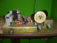
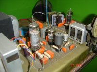
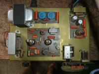
Very interesting, Osvaldo!Regenerative receivers have better audio quality because of less stages distorting the signal. I have a couple of them.
I recognize a EZ81 rectifier tube in the HV PSU and a ECL85 as the AF amplifier. But what's the 3rd tube, and what does it do? According to the dual rotary cap, is this a regenerative with two resonant circuits?
Best regards!
Admittedly I'm not too sure, as the perceptible difference between both is their heights, and there's no reference in the pic to compare with.
Best regards!
Best regards!
Very interesting, Osvaldo!
I recognize a EZ81 rectifier tube in the HV PSU and a ECL85 as the AF amplifier. But what's the 3rd tube, and what does it do? According to the dual rotary cap, is this a regenerative with two resonant circuits?
Best regards!
Yes. The third valve is a ECF801. The pentode "Amplifies" a little the signal incoming through the ferrite rod, and separates it from the regenerative stage, the triode inside it. Initially, I regenerated in the ferrite coil itself, but result in a very unstable mechanically. This solution performs very well for local broadcasting stations and some distant low power ones.
The rectifier is a 6X4. Neither EZ80 nor 81.
I have the schematic in ASCII art if you want it.
Last edited:
For sure I am. You've got my e-mail, don't you? Thank you!
FIY: My entrance to electronics has been a then (1970) popular German RADIOMANN experimentation kit. The biggest project was a regenerative radio around a low voltage EF98 tube, followed by a AF amplifier around the AC122 germanium transistor. So I got itched by radio designs from the beginnings.
Best regards!
... You will need to build, and tune inductors, and transformers for these frequencies, or procure a set from an old radio ....
Fellas, if someone really wants to try this and needs IF coils, drop me a PM. No need to cut up a working radio unless you just want to do that.
There is a little hamfest around here that frequently has NOS IF coils. The pic is the contents of just one sack I still had here at the office. I have more sacks ... I hate to see stuff like this head to a landfill ...
These are all 455 KHz, save one, but I know I have a bunch of 4.5 MHz, I feel sure I have some 10.7 MHz K - Trans including ratio transformers and maybe quad coils, and even 250-260 kc coils. I don't think I have any 21 or 44 MHz coils.
Attachments
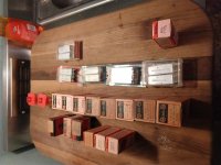
I know I have a bunch of 4.5 MHz
4.5 MHz was the "intercarrier" frequency for analog NTSC TV. They will work just fine for building an FM radio receiver with a 4.5 MHz IF, particularly if a complete set including the ratio detector or discriminator (quad coil) transformer can be found. The bandwidth for FM radio and TV audio are nearly the same.
and even 250-260 kc coils.
252KHz, 255KHz, and 262KHz were common IF frequencies for AM radios in the early days. These are another valid option for AM. The lower frequency will tend to have a narrower bandwidth thus chopping off more of the high frequency information, but providing better adjacent channel rejection. That's why they were often used in car radios.
...and also for old b/w and PAL colour tv's here in Europe...4.5 MHz was the "intercarrier" frequency for analog NTSC TV. They will work just fine for building an FM radio receiver with a 4.5 MHz IF, particularly if a complete set including the ratio detector or discriminator (quad coil) transformer can be found. The bandwidth for FM radio and TV audio are nearly the same.
Best regards!
- Home
- Amplifiers
- Tubes / Valves
- DIY valve radio