I have developed an interest in building my very own valve radio from scratch. I've built a lot of valve equipment, but I've never built a radio.
My wishlist for the project would be:
1) no SS components
2) FM capability
3) resistance tuned, no adjustable caps
4) octals look cool so go with them if possible!
I've looked thru a couple dozen radio schematics, and they all seem to have adjustable caps in them. Does anyone have any resistance tuned schematics to sugguest? Any other information for building a valve radio is of course highly appreciated.

Resistance tuned will be tough.
I'd start with an old edition of the ARRL Radio Amateur's Handbook.
I'd start with an old edition of the ARRL Radio Amateur's Handbook.
I had the same thought as you do, 3 years ago I started to build this receiver:
Pulse Counting FM Receiver
It got sidetracked by some other tube and speaker stuff and sits on my
workbench at 80% completion since then, i can't report about its functionality
unfortunately.
The project is rather well documented, appears to be working, and was
reproduced by other builders as the author reports.
If you're after a stereo FM-receiver, this build isn't for you as the bandwidth
is too limited to enable proper stereo demux. But IMHO FM-stereo was
rather a marketing gag. Lots of added demux complexity for rather mediocre
added value in terms of channel separation etc.
Kind regards,
Yves
I had the same thought as you do, 3 years ago I started to build this receiver:
Pulse Counting FM Receiver
It got sidetracked by some other tube and speaker stuff and sits on my
workbench at 80% completion since then, i can't report about its functionality
unfortunately.
The project is rather well documented, appears to be working, and was
reproduced by other builders as the author reports.
If you're after a stereo FM-receiver, this build isn't for you as the bandwidth
is too limited to enable proper stereo demux. But IMHO FM-stereo was
rather a marketing gag. Lots of added demux complexity for rather mediocre
added value in terms of channel separation etc.
Kind regards,
Yves
Not quite sure where you are coming from on the comment about FM stereo separation as it has generally seemed more than adequate to anyone I have discussed this with. I think the bigger issue with FM is the lack of stations broadcasting clean unprocessed signals - at least in my market area. (Limited bandwidth would be another.) An unprocessed live broadcast of classical or jazz can sound absolutely amazing. (I'm lucky to live near enough to get a strong signal from WGBH - one of the local PBS FM stations that does a lot of really high quality live broadcasting...)
@ OP WRT to diy tube FM tuners, this is probably a non starter unless you are very experienced with high frequency RF. Where are you going to get the required front end components, IFTs and other parts? Clearly the sensible thing to do is cannabalize a nice or not so nice working vintage tuner with all that might imply. Do you have a good FM RF generator, scope and other tools required in order to debug and align this thing? Do you understand how to layout and properly decouple all of the circuitry so that it does not oscillate at the IF and random RF frequencies you can't see with a conventional scope. (You need a scope with a 300MHz bandwidth to do this work and very low capacitance probes, etc.)
Getting the front end amplifier, mixer and oscillator to track properly over the entire FM broadcast band is not trivial. Have you given thought to how you would temperature compensate the local oscillator so that your tuner stays tuned to the station you want for more than a couple of minutes? You say you want to use varactors instead of a tuning capacitor, that's possible but requires some care in design to avoid modulating the signal you are tuning via the varactor supply. (Ask me how I know this... 😀 )
Doing a successful RF design and getting it to work will make designing a tube MPX seem relatively trivial by comparison - with the right test equipment and approach you actually have a fair shot at success.
I'd start with a simple AM superhet to get your feet wet and graduate if this goes well to an FM design later.
Even a superhet can present more problems in the execution than initially thought 🙂
Building a good receiver makes transmitters seem really, really easy.
Building a good receiver makes transmitters seem really, really easy.
Even a superhet can present more problems in the execution than initially thought 🙂
Building a good receiver makes transmitters seem really, really easy.
Particularly inadvertant transmitters..
 😀
😀I do have a thought - perhaps you can locate some of the old Danish (?) tube based Torotor FM tuner modules and restore them - making them the basis of your project. These were commonly used in Eico tuners, and I suspect several 60s era European manufacturers used them as well. They inlcluded various IF strips and front ends and were pcb based.
Decades ago I used an old heathkit FM tuner and in it's day worked fine, but some years ago abandoned this due to tighter station separation and poorer Q of the IF strip and the auto frequency lock which often captured the ajacent station. Free running LC oscillators have accuracy troubles when confronted with only 100Khz channel separation. Tough world, unless one lives around unconjested airwaves. Such tuners had relatively poor AM rejection, that is a strong signal on the side could be demodulated with the the signal one is listening to.
richy
richy
Some more information regarding diy tube FM receiver / Stereo decoder a.s.o. can be found here:
UKW-Projekt
German, but an online translator should get you going.....
Marcus
UKW-Projekt
German, but an online translator should get you going.....
Marcus
I have developed an interest in building my very own valve radio from scratch. I've built a lot of valve equipment, but I've never built a radio.
My wishlist for the project would be:
1) no SS components
2) FM capability
3) resistance tuned, no adjustable caps
4) octals look cool so go with them if possible!
I've looked thru a couple dozen radio schematics, and they all seem to have adjustable caps in them. Does anyone have any resistance tuned schematics to sugguest? Any other information for building a valve radio is of course highly appreciated.
Dude,
Your wish list does NOT compute! Radio tuning is done by LC resonant circuits. Either you vary the C or you vary the L, to change the resonant frequency. Resistive control of the resonant freq. requires varicap diodes and that means SS.
You can tune a radio by moving 1 or more slugs inside the inductor(s). Some cheapy car stereos have brackets connected to the tuning knob that move 5 slugs: 3 for FM and 2 for AM.
Alignment of superheterodyne circuitry requires a highly sophisticated test bench. AF work is easy in comparison. FM alignment is truly difficult, as sweeps across the band are required. Do you have a signal generator with VHF capability?
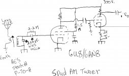
Build a "spud" AM radio for starters. That's very easy and not particularly expensive. I've uploaded a crude schematic for a slug tuned "spud" AM tuner. Not all parts values have been specified, but critical info. has been provided.
The data sheet/wiring diagram for the coil may not be correct. The winding with many turns gets connected to the pentode, while the winding with few turns is in the antenna circuitry. It's a step up tuned trafo. You will have to glue a stick to the tuning slug, to give yourself a station adjustment.
BTW, earth here means exactly that. A cold water pipe will usually do.
Attachments
AM radio is more straightforward to receive than FM.
Amongst AM radios there are a number of different topologies you can adopt, the simplest employing only a single tube.
You can build a simple crystal radio with a self-resonant coil and amplify it at AF. The inner tube from a kitchen towel makes an acceptable former for a medium wave coil.
You can build a 'tuned radio frequency' set.
You can build a 'regen' or 'super-regen' using positive feedback.
You can build a 'superhet' with single or dual IFs.
These have increasing performance in terms of selectivity, sensitivity, freedom from IM distortion, and other detailed specs which are probably of no immediate concern. AGC can be provided but again at the cost of complication.
Quite simply the most straightforward approach in any case will employ a tuning capacitor, possibly ganged tuning caps. 3 gangs are not uncommon. This is because some designs call for tuned circuits to track simultaneously as the knob is turned. You can obtain one of these from a hamfest, or simply raid an existing radio. It is obviously possible to use a varicap and a varying potential but this is a complication compared to a mechanically tuning cap. Inductor-tuned circuits are, in general, a PITA for amateur use.
FM radio has a slightly more complicated detector in it's simplest incarnation, the signal is converted to AM before detection.
You should be able to find loads of valve circuits, designs were common. Finding all the tubes for a complicated design might be another matter...
w
Of course FM radio is about 100MHz depending on country, which in itself calls for a bit more discipline than commercial AM (under 2 MHz).
Last edited:
Antique Electronic Supply (AES) has variable tuning caps , coils & antennas. I used to have links to saved websites, but lost them when my computer crashed. I found some really neat AM & FM transmitters you could build from AC run old 5 tube radios and just parts. There are a lot of Schematics on Nostalgia Air for free. I think a Pilot FM tuner from 1947 looked fairly simple. This is mono as stereo didn't come out till late 50's. You can sometimes find good deals on old radios on old radioclassified.com I picked up an RCA 7 tube AM/FM Table radio from 1949 for $65 with all extra tubes except 6V6GT. It has a transformer power supply which you want to look for. Works great, and even has an RCA input which works great with CD player etc. Something like that maybe a low cost start, which could be studied. One would hate to butcher it for parts though. I think the really old radio tube radios are neat to work with and restore, and you have something of vlue when your done. It looks like the full FM Band tuners came out in late 40's, but I've seen a Philco 1940 radio for sale with the partial FM Band. Philco seemed to use Loctals in the early 40's. Maybe hit the garage sales etc and gather up some good deals for low $.
Last edited:
Look up a older tube FM reciever with tube AFC (they do exist!) GE had a AM FM table radio that used a 6C4 (I think) triode to accomplish AFC. Instead of feedback from detector substitute a potentiometer in a voltage divider arrangement. Part values may need changing. Look MA, no variable capacitor or varicap diode. Have fun!
Mike
Mike
If you try to leap straight from audio to VHF construction (with added complications such as avoiding normal tuning arrangements) then you will either be very lucky or very frustrated. I know which is most likely! The way you posed your original question shows that you don't yet have the understanding to pull this off.
As others have said, start at the easy end with AM - maybe a TRF. Then try an AM superhet, perhaps for short-wave so you begin to get used to RF construction and alignment. The idea is that before you can get the answers, you need to understand the questions. If you have never touched RF before, then start with a crystal set so you can learn about tuning and impedance matching.
As well as understanding, you will also need some test equipment. A sig gen and some means of detecting RF - either fast oscilloscope or a diode probe and DMM.
RF is more fun than audio, but much harder to do.
I have a little different suggestion.
To learn about radio receivers, get an old Fisher or such receiver and put it right. Replace worn tubes, etc, and go through the AM and FM alignment procedure while studying the schematic. Better yet, go through this a few times with different gear. If you still want to design and build your own tuner after that (since no designs exist per your spec.) you'll have the test equipment and an appreciation of the technical requirements.
... 3.5 turn coil 1/8" diameter soldered between pin 2 and the chassis 1/4" away... don't accidentally disturb it or the alignment's off again...
I used to do this every day for a living so designing my own tuner is the furthest thing from my own mind but it would be a fascinating challenge.
Hey what about a multiband (shortwave) receiver kit to start with? Do these still exist?
Cheers!
Michael
@richwalters:
I would like to ask you what is that model of the famous Heathkit FM tuner (I heard that it has a "pulse-counting" FM demodulator) ?
I am also interested to see the schematic diagram, I don't know if it is on the Internet ... maybe if you have it, would you help me with that ?
In the hope of your answer, please allow me to wish you all the best!
Regards,
Cezar
Good evening dear Richie,Decades ago I used an old heathkit FM tuner and in it's day worked fine
I would like to ask you what is that model of the famous Heathkit FM tuner (I heard that it has a "pulse-counting" FM demodulator) ?
I am also interested to see the schematic diagram, I don't know if it is on the Internet ... maybe if you have it, would you help me with that ?
In the hope of your answer, please allow me to wish you all the best!
Regards,
Cezar
Designing an FM tuner that is tuned by a resistor requires a lot:
Inductors
Varicap Diodes (Varactors). The capacitance varies with reverse bias DC.
resistive dividers
single or multiple potentiometers.
There is a reason why almost all FM tuners use variable capacitors.
It is a major design problem to use varicap diodes in an FM tuner.
Inductors
Varicap Diodes (Varactors). The capacitance varies with reverse bias DC.
resistive dividers
single or multiple potentiometers.
There is a reason why almost all FM tuners use variable capacitors.
It is a major design problem to use varicap diodes in an FM tuner.
Eli had a good way to go.
Or,
Find an old AM vacuum tube car radio. Many of them were slug tuned.
Most of them had an RF amplifier ahead of the mixer.
Of course if you use that, you are re-inventing the wheel.
And as already stated, this is quite complicated, requiring lots of knowledge, and a well equipped RF test bench.
Or,
Find an old AM vacuum tube car radio. Many of them were slug tuned.
Most of them had an RF amplifier ahead of the mixer.
Of course if you use that, you are re-inventing the wheel.
And as already stated, this is quite complicated, requiring lots of knowledge, and a well equipped RF test bench.
Last edited:
If one wants to study slug tuned, look at the Collins R390 radio.
Lots of slug tuning.
Last used in Desert storm because static from blowing dust was killing the mosfet front ends of some other radios.
Lots of slug tuning.
Last used in Desert storm because static from blowing dust was killing the mosfet front ends of some other radios.
- Home
- Amplifiers
- Tubes / Valves
- DIY valve radio