How do you solve the antiskating in unipivot designs?
I think i saw the well tempered turntable a while ago, two years after i have built the water sliding linear tonearm , buti don't think i see any antiskating system working reliably in an unipivot system as it affects the azymuth at all times .Unlike the well temperate turntable design,it looks like you're using the air to damp the tonearm before it setteles which means it will oscillate a lot before settling unless the wires are rigid in horizontal plane which would kill all the unipivot tonearm advantages .Fixed bearings might not look cool from a resonance point of view or from , but it solves a lot of the problems and The well temperate turntable considered that viscuous silicon oil damping for a reason.The Most Ingenious Turntable from the 1980's - The Legendary Well Tempered Record Player (WTRP) - YouTube
My SUPA (Sideways Uni-Pivot Arm)) bearing is not a traditional uni-pivot. It is not free to roll like a uni-pivot because it is constrained laterally by the suspension. It therefore requires neither damping nor a high pivot point supporting mass to reduce the unwanted freedom to roll.
The pivot point is low (at or below record height) so that 'Torque Reactions Assist Contact' (the TRAC of SUPATRAC).
Bias applied by the bias rotor diminishes across the record to compensate for the gravitational force towards the equilibrium position in the bearing.
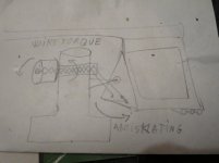
Indeed, from the few second of the clip on youtube i can't see too much tilting there, and, although not sure how well it works, maybe better with thicker wires , i thought maybe you'd like to consider a different antikating sytem by creating a toque through twisting the wires holding the tonearm against the unipivot.
Attachments
Last edited:
i thought maybe you'd like to consider a different antikating sytem by creating a toque through twisting the wires holding the tonearm against the unipivot.
I considered many methods of applying bias. The Firebaugh method which you describe does not work especially well on the Well Tempered decks. It can be adjusted only by changing the length of the suspension filament and I suspect that some users may end up with off-centre cantilevers as a result of inappropriate bias.
As I said, the bias mechanism which I devised compensates for the fact that the arm bearing has an equilibrium position. The Firebaugh method could not do that. Firebaugh arms are a turn away from reaching an equilibrium position when properly installed.
Maybe that didn't work with the commercial long tonearm because the counterweight is too far from pivot?More counterweight closer to the pivot might work easirer.
I considered many methods of applying bias. The Firebaugh method which you describe does not work especially well on the Well Tempered decks. It can be adjusted only by changing the length of the suspension filament and I suspect that some users may end up with off-centre cantilevers as a result of inappropriate bias.
As I said, the bias mechanism which I devised compensates for the fact that the arm bearing has an equilibrium position. The Firebaugh method could not do that. Firebaugh arms are a turn away from reaching an equilibrium position when properly installed.
Succinctly put 🙂
I'm not sure what you mean. The Blackbird counter-weight contains 5 tungsten bars which can be individually removed so it is always possible to keep the counterweight close to the pivot. Effective mass is fairly low so the arm is supplied with an inertia weight which enables you to add effective mass for less compliant cartridges.
The issue of bias equilibrium arises because gravity settles the arm in an equilibrium position. You can rotate the arm pillar so that this equilibrium position is near the end of the record. The sideways force on the arm due to gravity is approximately linear with deflection from the equilibrium position in the working range so the bias mechanism needs to supply extra centrifugal bias at the beginning of the record and almost none at the end. The mechanism is adjustable so that both the difference between applied bias at start and end positions can be changed, and the average bias can be changed. This allows appropriate bias to be applied taking into account the changing bias of the bearing as it rotates.
As you probably know, correct bias varies with many factors including signal strength, so approximately correct bias is all you can hope for with any pivot arm which does not have a real time active bias system. I am not aware of any pivot arm which has that, and given the problem of latency it might constitute a form of distortion in its own right.
The primary issue therefore is to set net bias so that your cantilever still hangs straight after 1000 records and the stylus is equally worn on each side.
Succinctly put 🙂
Thank you. I have given all this some thought.
My comment was about the place of those tungsten bars which are pretty far from the pivot and removing them will not work in your favour cause the closer you get to the pivot, more counterweight is needed, so you can't remove them to balance a heavier tonearm+ cart complex, you need to bring them closer to the pivot instead and put more bars than you already have.The closer they are, the lighter the effective mass of the tonearm you get, so instead of 4 bars you'll need maybe 5 or 6 bars closer to the pivot , yet your tonearm gets lighter with that mass increased and the twisted wires torque would be also higher with the counterweight closer to the pivot so less twists are needed.
According to Tejinder document, if we consider an x(horizontal side to side), y(horizontal front to rear) and z plane(vertical), your counterweight would better be as close as posible to the pivot and distributed as much as possible only in the x plan , so your bars should be groupped together in as less space as possible closer to pivot.The whole counterweight you are using might look cool, but it's in contradiction with the most fundamental study in tonearms world...I just hope that the beneffits of your design can fight the counterweight downsides.Apparently your first diy tonearm was closer to the optimum design than your commercial iteration.
You made me really curious about your tonearms and i'm willing to try your design with my flabby flat tonearm and sliding antiresonant counterweights trying that sort of Firebaugh(now i know the guy's name and also found a complete document with all types of antikating techniques after putting that name into Google earch box, so Thank You for that!) although i'll be using it in a different way.I'd simply like to see how it works compared with a more classical gimbal system as it's fairly simple to build and try.
By the way i might need some tungsten bars myself just don't know where to get them for cheap 🙂
I use four tungsten bars with most of my cartridges on a 9 inch Blackbird, but the standard grip now holds five. Five bars would put the weight too close to the pivot, fouling the wires. Most heavy cartridges are not very high compliance so the reduction in effective mass which comes from grouping the bars closer to the pivot isn't useful in real situations. Less effective mass isn't always better because you can have too little and bass loses its heft. As I said, the 9 inch arm is light enough. I even supply an inertia weight to add mass. I use it even with cartridges like AT VM540ML which is on the compliant side.
What I'm trying to say is that using the five-bar tungsten grip on the 9 inch Blackbird gives quite low effective mass and there is little to gain by taking effective mass yet lower.
The wiring is very compliant Litz and as long as the arm is set up right I don't think they contribute much if anything to bias.
P.S. I've just measured and the four tungsten bars range from 1cm to 3cm from the pivot. I wouldn't call that far. The real issue is whether you have an appropriate effective mass for the cartridge. During development I used a Shure M97xE quite a lot, with the brush removed. It's one of the most compliant cartridges I know and the Blackbird works beautifully with it. You don't need the Blackbird's additional inertia weight with the M97.
Last edited:
Thank you. I have given all this some thought.
Not only thought. Looking at the design, I can also see all the details you must have tried and discarded as well. What remains is clearly just a small fraction!
I'd like to see what you have in your "tonearm morgue" 😀
Best regards,
Mike
Not only thought. Looking at the design, I can also see all the details you must have tried and discarded as well. What remains is clearly just a small fraction! I'd like to see what you have in your "tonearm morgue" 😀
Here are a few prototypes in the graveyard:

I was somewhat taken aback by how good the first prototype sounded. I ran it on the same deck as my Ekos 2, simultaneously, and the advantage was already clear. They have all sounded consistently excellent, which leads me to believe that the principle cause of the advantage is the uncompromised stiffness and the bearing design.
Thanks for posting the photo. In chronological order, looks like?
Yes, inadvertently the arms are chronological left to right and the pillars are right to left including the one mounted in the plinth.
I had an enquiry about a protractor. The SUPATRACTOR (! ;-) is included in with each arm. It enables calibration of spindle-to-pivot, pivot-to-stylus (overhang) and offset alignment. It should be all you need to set up geometry on the record plane. Here's a pdf of the Linn geometry version:
http://www.supasound.com/protractor_linn.pdf
http://www.supasound.com/protractor_linn.pdf
An updated manual is here:
http://www.supasound.com/manual.pdf
It contains some new information, including a technique for lining up the three pitch axis points using a piece of paper.
http://www.supasound.com/manual.pdf
It contains some new information, including a technique for lining up the three pitch axis points using a piece of paper.


- Home
- Vendor's Bazaar
- DIY tonearm project going commercial