Where did the last few posts go???

The reply that immediately followed your last post was deleted by the poster themselves a few minutes later. It was within the normal 'edit window' time and they have the ability to do this if they wish.
The other two posts were the subject of a moderation issue and deleted accordingly.

@mbrennwa
,
I wanted to touch base with you here in public, the hoard of VFETs was amusing and I was feigning being jealous about them. I would never post something with malice, it was supposed to be funny. The written word can be read many ways, I obviously missed the funny bone with that one.
I apologize to anyone who was offended, it was not my intent to do so. 🙁
JT
@thompsontechs No worries! I did not think you'd be offending me at all. I guess the mods overreacted a bit. 😎
I should have been more clear, it was flagged, and the mods did their thing, all good. Next time, I have a smart as remark, I will send it to you PM. 😛
How did they test out?
How did they test out?
They all tested good, with some nice matches. I am currently also looking at some more Sony VFETs I got from @Bones13 .
Once I've got them all tested I will decide on my plans to build a Sony Comemorative clone and select the parts for this. The remaining parts will be available for anyone who wants them.
Once I've got them all tested I will decide on my plans to build a Sony Comemorative clone and select the parts for this. The remaining parts will be available for anyone who wants them.
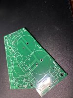
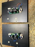
Now it’s time to replace the prototype with the final pcb obviously after drilling and tapping the final holes 🕳️
Once all is working I will share the gerbers for those that don’t mind soldering a few smd parts.
Once all is working I will share the gerbers for those that don’t mind soldering a few smd parts.
Attachments
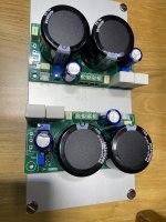

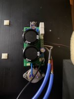
@schultzsch It's a bit hard to see on the photos, but it looks like there is no gate stopper resistor on those SITs. Those long wires will like to pick up noise, so I think a stopper resistor on the gate pin of the VFET parts would be a good idea.
So how's it sounding @schultzsch ? I have spare pair of Tokins and will be interested in your schematic and gerbers when you're ready to share them.
I had an AJ for 10 years. I liked it’s sound very much but in the end I decided to replace it with the excuse that for nowadays electricity prices it was drawing too much current.(the aleph was drawing 200w/channel)
So for one year I played with the output stage of the xa252 and then built the complete amp.
Not long after finishing the xa252 I wanted to hear how those vfets sound that I stashed for years.
Well… even if they give higher thd compared to the xa252, since I built the vfet follower the xa252 was turned on a few times and not for long. I use it only when high power is needed but it seems it’s never needed. For my listening levels 5w it’s already very loud.
One thing that I like about the vfet amp is that when driven to high levels and it starts to clip it does it very softly compared to the xa252.
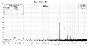
Another thing that I like is that I can set its power supply voltage depending on how loud I plan to listen and also depending on how much thd I want. For example at 17v it gives 1% thd into 1w/4r, for 24v it goes to 3w/4r and 1%, for 30v it gives 1% at 6w/4r the values being close into 8r too.
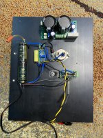
I am using a buck boost converter to power up each channel.
Except the vfets the rest of the amp is cheap to build so if you have them it’s a shame not to build it.
But wait… the pcb supports also a mosfet or a jfet(sjep120r100) in place of the vfet, you could try it with any of these and then compare what is best for you. Or you could biamp with mosfet/jfet on the low and vfet/jfet on the highs or as you wish.
To go cheap you can start with the mosfet version first.
Now you have an excuse less not to try it.
I will come back later today with the schematic and gerbers and also will explain better what I did.
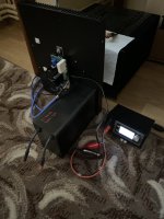
Ps. The 12v battery was used on the first prototype, now it serves only to hold the amp heatsink in place. Probably one day will try to power it with 36v comming from batteries.
So for one year I played with the output stage of the xa252 and then built the complete amp.
Not long after finishing the xa252 I wanted to hear how those vfets sound that I stashed for years.
Well… even if they give higher thd compared to the xa252, since I built the vfet follower the xa252 was turned on a few times and not for long. I use it only when high power is needed but it seems it’s never needed. For my listening levels 5w it’s already very loud.
One thing that I like about the vfet amp is that when driven to high levels and it starts to clip it does it very softly compared to the xa252.
Another thing that I like is that I can set its power supply voltage depending on how loud I plan to listen and also depending on how much thd I want. For example at 17v it gives 1% thd into 1w/4r, for 24v it goes to 3w/4r and 1%, for 30v it gives 1% at 6w/4r the values being close into 8r too.
I am using a buck boost converter to power up each channel.
Except the vfets the rest of the amp is cheap to build so if you have them it’s a shame not to build it.
But wait… the pcb supports also a mosfet or a jfet(sjep120r100) in place of the vfet, you could try it with any of these and then compare what is best for you. Or you could biamp with mosfet/jfet on the low and vfet/jfet on the highs or as you wish.
To go cheap you can start with the mosfet version first.
Now you have an excuse less not to try it.
I will come back later today with the schematic and gerbers and also will explain better what I did.
Ps. The 12v battery was used on the first prototype, now it serves only to hold the amp heatsink in place. Probably one day will try to power it with 36v comming from batteries.
Attachments
Have you tried a V+ higher than 36V - I have a complete cap multiplier power supply available at, IIRC operates at 45V. Obviously a little research and experimentation will answer the question but just trying to get an initial feel...
As it happens, I'm also working on a project to build Nelson Pass's 'got VFETs' design using Sony 2SK60 devices, so a nice comparison.
As it happens, I'm also working on a project to build Nelson Pass's 'got VFETs' design using Sony 2SK60 devices, so a nice comparison.
This buck boost goes only to 36v so that was the highest. If you use 50v rated caps you could go to 45v rails but do you really need it? You will need also a pretty big heatsink.
There is a thing you must account for when increasing rail voltage and sit vds.
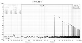
As you increase the vds of the sit the 2nd hd will go down(cancel) much more than the 3rd. So it will become 3rd dominant at least at high power levels.
To have it 2nd dominant on the entire power bandwidth you have to increase the bias proportionally to vds.
With 1.8a you are good(2nd dominant)up to 36v and 15w/4r.
Right now the phase of the 2nd is positive so I reversed the terminals on my speakers.
It is possible that above 36v the phase will become negative.
Beside the sit vgs and bias adjustments I added an adjustment(with ZM’s help 🙂 ) that selects how much the ccs contributes to the output current or said with Pa’s words an adjustment that tricks the vfet to think he powers a higher load.
There is a thing you must account for when increasing rail voltage and sit vds.
As you increase the vds of the sit the 2nd hd will go down(cancel) much more than the 3rd. So it will become 3rd dominant at least at high power levels.
To have it 2nd dominant on the entire power bandwidth you have to increase the bias proportionally to vds.
With 1.8a you are good(2nd dominant)up to 36v and 15w/4r.
Right now the phase of the 2nd is positive so I reversed the terminals on my speakers.
It is possible that above 36v the phase will become negative.
Beside the sit vgs and bias adjustments I added an adjustment(with ZM’s help 🙂 ) that selects how much the ccs contributes to the output current or said with Pa’s words an adjustment that tricks the vfet to think he powers a higher load.
Thanks, and yes you're right, I don't really need 45V rails, I was only asking as I have the power supply available so potentially a quick build option, but on reflection I can just use the SMPS I have for the 2SK60 project.
I like you're suggestion of bi-amping using the JFets for the mid/top and MosFets for the bass - I have some Pass SLOB speakers. Hmm...
I like you're suggestion of bi-amping using the JFets for the mid/top and MosFets for the bass - I have some Pass SLOB speakers. Hmm...
A big thanks to Pa for sharing the schematic and to ZM for helping me to implement the easily adjustable ccs modulation.
Now maybe you will wonder why I used the small ccs. Well because having a resistor there and the rails that go from 17v to 35v will change a lot the bias current and it`s not what I wanted.
VR3 adjusts how much you fool the vfet 🙂
Now maybe you will wonder why I used the small ccs. Well because having a resistor there and the rails that go from 17v to 35v will change a lot the bias current and it`s not what I wanted.
VR3 adjusts how much you fool the vfet 🙂
Attachments

- Home
- Amplifiers
- Pass Labs
- DIY SONY VFETS pt 3 - Got VFETs?