you can put the second filter on input/driver pbc...Can't comment on your build as I don't know how much current it draws.
However, on Papa's 1st lottery VFET, I successfully used 2 of Mark's excellent filters, that is 1 per channel.
Just for information:
- I tried with one for both channels, something I did well knowing I was driving very slightly overspecced and something I would NOT recommend other than for testing purposes when you know what you are doing. I also knew well what components could withstand in real life for this test. Bottom line, it sounded better and but less so than with 2 filters (1 per channel).
- 2 filtersn, that is 1 filter per channel, sounded best and was well within the filter's specs. It is not the first time I noticed that these excellent filters sound at their best when well within their specs, which is of course no wonder, regardless the (higher) ampere rating of their components etc.
- I tried 4 filters, that is 2 per channel, cascading them. Sounded slightly worst than 1 per channel to my ears and the other listener involved. Of course that is very amp dependant.
All these combos were tried with short cables and connections enabling very quick changes between configurations and blind listening thanks to the other operator.
I would go for first with 1 filter per channel, that is 2 in total in your case, provided you are still well within the amp rating of the filters. Then of course you may want to experiment. My bet is also that separate filters for each channel help somewhat separating the channel PS... perhaps.
I hope this helps
Claude
There is this thing about the power supply filters.
RAW from the brick with juts one filter (0,23 mH/330 µF) it is great; then I have the impression that adding capacitance changes sound. I have now +10.000µF after the filter. (Why: It is a simple way to avoid a thump - the Vb drops gracefully.)
But the extra cap does change sound, the amplifier gets 'darker', is my impression. Not is a bad way though. The highs are very fine. Others with better listening experience should comment.
- How would a large capacitor bank like 6 cans*56.000 µF sound? How would a BIG battery sound? These are the experiments done in the beginning of the '80ies. My first Le Monstre (Hiraga) had some 16 of those large cans . . and each additional cap improved the sound.
Quote: you can put the second filter on input/driver pbc...
Thanks for the hint, kind of you...well, as things are,I can expend on that...
I did try quite a few mods on my VFET.... and some didn't bring the expected results. One mod was to bypass entirely the input board, driving directly the VFET OS. For sure the FS with transformers etc. could only rob musicality, plus I wanted to experience VFET pure. I had all the parts, the switches to enable quick swaps (in case I really would need more gain one day), impedance and gain structure wise all was clear from the DAC source... Everything was green for the tweak of the year LOL
Guess what - it made no difference at all. And I tried really hard, and wasn't alone listening. Don't ask me why, it still confuses me, but at the end I reversed everything to standard.
I saw back then only 2 logical conclusions, not excluding each others BTW :
1- Papa did a splendid job with a FS that blends perfectly with the OS... wouldn't be suprprised now that I think of it, GLOL
2- The sonic signature of the VFET OS is strong so that it overweights the FS' one. Please note I am of course not saying that playing with Mark's various and certainly excellent front stages isn't going to make any difference - that's a completely different debate! I am only saying that in my case taking the original FS completely out of the signal path didn't change anything to my ears on a secondary HIFI system "made" for the VFET (D70S DAC, Klipsch RP8000F LS).
Bottom line: I am not worried regarding the original FS PS 🙂
From all the tweaks we tried, Mark's filters and also adding decoupling PS caps on the OS board were the most rewarding, by FAR.
And they did make quite a difference to my ears, not a subtle one.
Enjoy music
Claude

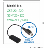
What is a good, easy to wire aviator type female connector for the wall wart R7B. I got one, but the connectors that the internal wires connect to are miniscule and unusable. Male r7b to female r7b (that can be attached to chassid) to some easy to solder wire posts/clips for the power supply i.e. how do I connect this thing to an attachment attached the chassis and have wires going to the board. Something easy to handle and solder the wires to?
Attachments
dunno, maybe this will give you idea how to make it different:
https://www.diyaudio.com/community/...-pt-2-n-channel-assembly-by-mighty-zm.385977/
https://www.diyaudio.com/community/...-pt-2-n-channel-assembly-by-mighty-zm.385977/
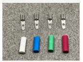
Well, I suppose I can use phono color coded cartridge clips tied directly to the pins and attached with 18 g wire. There would be no interface, I would have to secure the wall wart r7b end. They would be detachable with tweezers like a phono cartridge LOL. It would be nice to have a reasonable and rugged aviator type attachment, though, that could be tied to the chassis and has good sturdy leads for attaching to the internal wiring.
The jewelery, bits and logistics assembly phase of this is going to take longer than the various soldering and board testing rituals. I'll have to channel some artisan skills that I am not sure are there.
The jewelery, bits and logistics assembly phase of this is going to take longer than the various soldering and board testing rituals. I'll have to channel some artisan skills that I am not sure are there.
Attachments
You should read the DIY SONY VFET Part 1 & 2 threads, there are a number of ways other members have connected the brick to the amp. In part 1, the chassis mount connector for the brick is discussed with the part numbers from Mouser and Digikey. A couple of nights of reading you may find the ideal solution.
Another pic of the piece. Does anybody have a quick and dirty inventory and order number so I don't have to wade through hundreds of pages?
Would this be the piece? https://www.digikey.com/en/products...bkjCG1PoQtlPzMLp9Ryno_RS5vFzsU7xoCCuwQAvD_BwE
Would this be the piece? https://www.digikey.com/en/products...bkjCG1PoQtlPzMLp9Ryno_RS5vFzsU7xoCCuwQAvD_BwE
Attachments
Last edited:
Hi cjfrbw,
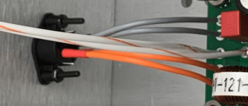
the one in your post #289 from Digikey is exactly the one I've got for my chassis as well. Soldering cables up to probably AWG 16 worked well enough for me (tip: insert the mating connector into the jack before soldering. That way, if the plastic gets slightly soft during soldering, at least it doesn't shift the connectors).
Here's the Mouser link to the connector as well:
Kycon R7B chassis-mount jack
Best regards, Claas
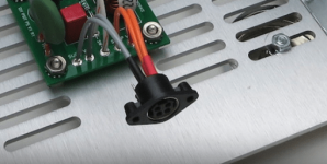
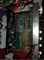
Well, I have everything ready to wire up and test the first channel in the TA 4650 chassis. Adapting the chassis itself with holes and bits hasn't been a trivial task. Ergonomics I guess isn't my thing. It was much easier building and testing the cards/VFET/MOSFET etc. I am so impatient. Wiring that little R7B thingie was a pain in the ***. Both wired channels are emitting 36V, so far so good on the wall wart.
Attachments
Last edited:
I hooked up the first channel. Transistors heated up the heat sink over 30-40 minutes to 105 to 120 F by temperature gun. I double, triple, quadrupled checked the hookups. The card I already tested on the bench and it worked fine. Now, it doesn't produce sound when I link up to speaker. It makes a contacting noise when connected, but no signal.
However, the mystery is, when I touch the positive speaker lead to the 'input', I get an amplified signal through the speaker. So, no amplified signal when 0+ and 0_ connected, but an amplified signal when speaker + touches I+. So, did something get lost in the signal transfer across the card? How is the input + creating an amplified output, while still being connected as the input?
Again, this card when bench tested worked to produce sound just fine when hooked up.
False alarm. Idiocy reigns. Strange thing is, it was an idiocy I already did once. Guess once burned, twice unwise. Fortunately, it does not appear to be of the flaming and smoking variety and the card is OK. Accidentally connected the two transistor Grounds with metal screw from board. Plastic screw fixed it.
Hooked it up inside the TA4650 chassis correctly, first channel makes nice music through the test speaker. I tried the internal preamp signal, too, connected to the input of the VFET card, and it works great as an input driver. Gets pretty loud at 2 o'clock on the Preamp dial. That means the functions of the TA4650 preamp are available to the VFET amp, or, the VFET amp can be used without the Preamp through the separate amp input.
I'm beginning to think this is going to work.
I left it on for an hour. Heat sinks seem to stabilize @ 110 to 115 or so in the hot spots. I don't know if the T of the transistors themselves matter, it seems most take temperature from the heat sinks, but the transistors seem about the same as the hot spots on the heat sink. I can keep my fingers on the hot areas lightly for over 8 seconds or so. The outer ends of the heat sink seem to be about 95 on one end and 105 on the other.
I think that makes it OK.
I think that makes it OK.
Connected second channel and it is making music, yay. Next, put power and output on both cards and test stereo output, let heat sinks cook and see where they wind up. I am guessing equilibrium will be 120 to 125F or so adjacent to the VFETs.
If all that goes well, then replace alligators with hard wiring and place wall wart supply on channels instead of external power supply.
If all that goes well, then replace alligators with hard wiring and place wall wart supply on channels instead of external power supply.
Attachments
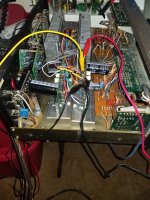
Both channels hooked up and making music. Even with alligator clips, very nice sound quality. Detailed without being etched. Hard to stop listening in stereo, very nice in upper midrange, very sheer and delineated. Excellent sound staging within this sort of desk top setup. I guess you could call this the baby relative of the SIT 2. This with a couple of old Optimus mini speakers three feet apart at about four feet away.
Hot spots on heat sinks seem to measure out to 130 F to 135 F, with range over the heat sinks from about 100F upwards with different areas measuring differently. They don't seem to be giving a huge heat blast yet when I hold my hand over them. My M2 with few active devices seems to be about 120 at the heat fins. The Pass type DIY Sony push pull gets very hot, out to about 130 to 135 F at the heat fins. Don't know if these temps are survivable for the devices, but I guess I'll find out.
I'll take a break and do the final hard wiring next week, recheck the bias etc. The power supply indicates about 2.7 amps @36V with both cards working.
I am going to call it for the heat sinks at 130 F plus or minus a few. More listening, this thing sounds REALLY good, even through the ancient preamp section of the TA 4650.
Last edited:
Well it’s dark, wet, and chilly outside so that means that it is time to start sorting parts and studying semantics for my build of the VFET amp.
DIY VFET boards and parts kit…check
Meanwell power supply…check
4U chass…check
PSFilter from Mark….check
Scourge FE…check
Missouri FE…in the mail
2SJ18 VFETS..check.
New digital soldering iron…check.
Onward.
Thanks for the excellent encouragement from you all and to NP for his generosity.
My ACA mono blocks sound great to my ears, and am looking forward to the VFET build.
NP mentioned earlier that he would be developing some new input boards that would be very small in foot print. Has that happened yet?
- Home
- Amplifiers
- Pass Labs
- DIY Sony VFETs OS2 Official thread