Vinegar may also work ,use it on my hard water deposits.
Vinegar is nice, because it can evaporate fully without leaving behind corrosive residues. Otherwise, just be sure to thoroughly rinse away whatever cleaning agent you're using!
The way the hole pattern is used, you can move it all the way back and have the inputs face the RCA Jack, or you can mount next to the OS and input is facing OS. I grappled with both, then decided for the option closer to OS (but flipped and mounted with two screws)
I flipped and mounted mine all the way to the back. It seemed like that was the way it may have been designed, so I just rolled with it. A bit snug, but it all fits nicely.
Edited to remove an odd multi-quote.
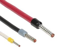
Oh, one more thing - very important to a good crimp is that the mating metals are nice and clean. Ideally, use freshly-stripped wire which you have *not touched* with your fingers, depositing skin oils. Hopefully the inside of your connector barrel has never been corroded or in contact with anything which will contaminate the connection (so, best to use relatively new / good crimp terminals, not old crusty ones).
I flipped and mounted mine all the way to the back. It seemed like that was the way it may have been designed, so I just rolled with it. A bit snug, but it all fits nicely.
Edited to remove an odd multi-quote.
I was worried that it would crowd the speaker jacks, but yours looks great.
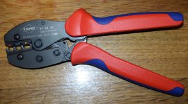
About crimping and crimp tools I use this one which has always worked perfect if the correct gauge wire is used for the crimp connector. The crimp connector must have the correct DIN specification (or another similar norm). The best crimp connectors are those has has a built-in copper ring as copper will harden during the crimp pressure.
Attachments
I think a company like AudioQuest uses crimping for all their connectors and they markering department claims it is "much" better than a soldered connection. That said I am fully happy with soldered connections 🙂


Pro tip: On the subject of crimping vs. solder connections, one should always use one or the other connection technique; never both. It's a myth that doing both is better.
A good crimp connection is generally more reliable than a soldered connection, since a proper high-pressure crimping tool will achieve a gas-tight "cold weld" between the crimp-on ferrule and the wire metal. This not only achieves a very low connection resistance, but keeps out environmental contaminants which might corrode the connection. The crucial factor is using the right tool - I highly recommend using a ratcheting-cam type crimp tool in order to get adequate leverage & force at the die to make a proper connection. Inexpensive rigid plier style tools can be inconsistent, and many users don't apply enough force.
Unfortunately, if you attempt to solder an already crimped connection, you're likely to do more harm than good. The application of heat will relax the stresses in the crimped metal which are holding the connection tightly together, degrading the crimp strength. Further, the solder is unlikely to properly penetrate the full mating region, whilst intrusion of fluxing materials which cannot be cleaned out into the small gaps opened up by the thermal expansion of the two crimped metals introduces active chemicals which can lead to premature corrosion. For this reason, crimp+solder connections are generally forbidden by code / regulation in many if not all safety-critical applications.
Solder by itself is also a perfectly fine connection technique, and one which is easy for us DIY-er's to accomplish (and inspect) with good consistency. However is widely recognized as less reliable than a properly-executed crimp (though probably not enough to matter in our use cases, so long as you can solder with enough skill to avoid cold joints).
Google will surface loads of good in-depth info for anyone curious to learn more.
thank you for your detailed and without doubt, well informed reply
though - no paper in the world can convince me that crimping across plastic sleeve is effective crimping
I'll proceed with my routine - whenever I use ring or needle wire end/connector/lug/name it - if there is plastic sleeve I remove it, "crimp" with simple mini-pliers (so without excessive force) , then properly solder, then heatshrink for beauty and coloring reasons
end result is much more soldering in proper tight space than crimping
seen innards of so many gadgets ranging even from WWII, plenty of connections made exactly in same way , having proper contact even today
ok, overall tropicalisation certainly helped
I'll proceed with my routine - whenever I use ring or needle wire end/connector/lug/name it - if there is plastic sleeve I remove it, "crimp" with simple mini-pliers (so without excessive force) , then properly solder, then heatshrink for beauty and coloring reasons
I use your method too, depending on what I have on hand. Especially for the needle/wire connections (fat wire to small thru hole)
I haven’t tried that yet, but will soon. I’ve swapped AJSS into system so I could do some back to back comparisons
In many audio sources and preamps outputs absolute signal phase is a mystery 😀
It seems the skill of the constructor is critical in both soldered and crimped terminations. Either way done improperly can result in a low reliability connection. Done properly, crimped connectors provide a cold welded and gas tight connection between the wire and the crimp ferrule. Gas tight means the connection is not prone to oxidation at the interface. They also provide better strain relief for mechanical stress between the wire and the PCB. They both have their place but when doing dozens or hundreds of connections, I would have to say that crimped is faster and easier. The correct crimp tool is critical for the specific matching crimp connector. As a result, one can end up with a cabinet of over a dozen crimp tools for various connectors.
The three most common ones that I find useful for DIY audio projects in my experience are the “Faston” female connectors used for high current power, speaker, and grounding connections, Molex KK for smaller signal wires or low power DC for ancillary components, and Molex pin and socket type used in quick connect plugs and PCB mounted sockets (these are often found on computer MB connectors and disk drive power connectors). There are people who say “the best wire connector is no wire connector.” 🙂 True - but that’s not very practical for DIY unless one can make a single PCB with hard mounted connectors soldered on.
One of the biggest disadvantages of soldering a connector that has a crimp terminal is that the solder wicks up the wire and stiffens it to make a “solid wire”. Solid wires are only used on architectural/houses/buildings as they don’t move or vibrate much. Vibration or strain will eventually cause a solid wire to fatigue and crack. Connectors designed specifically for solder terminations will have a solder cup and an extended mechanical strain relief system that extends beyond the solder wick point. Usually a clamp and rubber grommet.
So for a PCB only fitted with flying lead solder joint holes, what can be done to improve the connection reliability and reduce mechanical strain in the wire? A crimp to pin connection. This provides the cold welded joint between the wire and the connector and a strain relief. The solder joins the connector to the board and does not let solder wick up the wire. Yes, yet another connector and associated crimper tool. But for $20 to $30, I think this one is a good one to have and will be well used.
The crimp pin termination looks like this:
The tool looks sort of like a camera iris on steroids:

Example of one you can get as kit with connector pins:
https://www.amazon.com/dp/B07XBLGPC...abc_DC3N2R3CQP1QRKGEQ0ZN?_encoding=UTF8&psc=1
The three most common ones that I find useful for DIY audio projects in my experience are the “Faston” female connectors used for high current power, speaker, and grounding connections, Molex KK for smaller signal wires or low power DC for ancillary components, and Molex pin and socket type used in quick connect plugs and PCB mounted sockets (these are often found on computer MB connectors and disk drive power connectors). There are people who say “the best wire connector is no wire connector.” 🙂 True - but that’s not very practical for DIY unless one can make a single PCB with hard mounted connectors soldered on.
One of the biggest disadvantages of soldering a connector that has a crimp terminal is that the solder wicks up the wire and stiffens it to make a “solid wire”. Solid wires are only used on architectural/houses/buildings as they don’t move or vibrate much. Vibration or strain will eventually cause a solid wire to fatigue and crack. Connectors designed specifically for solder terminations will have a solder cup and an extended mechanical strain relief system that extends beyond the solder wick point. Usually a clamp and rubber grommet.
So for a PCB only fitted with flying lead solder joint holes, what can be done to improve the connection reliability and reduce mechanical strain in the wire? A crimp to pin connection. This provides the cold welded joint between the wire and the connector and a strain relief. The solder joins the connector to the board and does not let solder wick up the wire. Yes, yet another connector and associated crimper tool. But for $20 to $30, I think this one is a good one to have and will be well used.
The crimp pin termination looks like this:
The tool looks sort of like a camera iris on steroids:
Example of one you can get as kit with connector pins:
https://www.amazon.com/dp/B07XBLGPC...abc_DC3N2R3CQP1QRKGEQ0ZN?_encoding=UTF8&psc=1
Last edited:
Follow the color wiring diagram. The DC power conn has six pins, and two of those are connected to the chassis and cable shield. The connection to the chassis is made on the small power filter PCB.
The dc power panel connector has 4 pins that you solder wires to as well as a "pin" on either side of the connector. Look at 6L6's guide and you will see what I mean.It looks like the pins on either side may be for soldering the connector to a circuit board.In addition it looks like they are attached to the metal sleeve in the panel connector.If that is the case I checked online and the MeanWell plug metal sleeve is attached to the negative(2) pins of that plug,i'm not talking the panel connector,i'm talking the male plug on the power supply.You can go online and check,it states the sleeve is connected to the -ve pins.So if you try and connect one of those "outer" pins on the panel connector to the chassis you will have shorted out the thermistor due to the 2 negative plug pins being connected to the plug metal barrel. I'm not sure why the color wiring diagram shows those pins being connected but don't do it.If anyone has followed that diagram then there should be a warning notice put out.
Last edited:
I was curious about this also, and I appreciated your previous posts. I did not want to disagree with your "red herring", when I think you were/are onto something. I can confirm with a DMM and the attached that the "tabs" once the male plug is inserted are continuous with -Vo and mains earth.

Per the attached schematic below showing that the thermistor is between chassis GND and -Vo, (and also verified with a DMM), I believe you are correct. Thus, I chose to leave out that section of the wiring until it was 100% confirmed that I was not shorting the thermistor.

Everything from me... should be taken with a grain of salt as a newcomer to electronics, but that is how I thought it through and how I came to the conclusion and thus the choice I made for my personal build.
BTW - It makes LOVELY music, and I haven't shocked myself into oblivion by leaving out that specific wiring.

Per the attached schematic below showing that the thermistor is between chassis GND and -Vo, (and also verified with a DMM), I believe you are correct. Thus, I chose to leave out that section of the wiring until it was 100% confirmed that I was not shorting the thermistor.
Everything from me... should be taken with a grain of salt as a newcomer to electronics, but that is how I thought it through and how I came to the conclusion and thus the choice I made for my personal build.
BTW - It makes LOVELY music, and I haven't shocked myself into oblivion by leaving out that specific wiring.
Ok,thanks for verifying this.So then the wiring diagram should be modified or people made aware NOT to connect those tabs to anything ,which is what 6L6's picture shows but is in disagreement with the wiring diagram.

EDITED* PERSONALLY GOING TO WAIT AND SEE ON THIS, SOUNDS LIKE IT'S NOT A BIG DEAL (TO NOT ADD IT).
Per Nelson:
“Probably we should have included a lug.
Doesn't have to be done, but it's good practice to make that connection, even
though the power supply meets international isolation safety requirements.”
Last edited:
If you look at the filter schematic and with the info I have just presented then if you follow what you have posted then you will have shorted out the thermistor,its a mistake.
The Eagle has landed...well at least the first half of it.
That was pretty fast considering that I think I was the last name drawn from the hat.
I was lucky enough to be close to the shipping origin in MA.
Strangely, the package left MA, went to RI and then back to MA before coming to me in CT. Oh well, who cares?
I did a quick check on the contents looking at the boards for issues that have popped up already.
It looks like the silkscreen for C1 on the OS boards is as it should be.
The FE boards have R7 present.
Anything else I need to remember to check?
I’ll be doing an inventory of the packet contents, testing and labeling resistors etc once I can finish a little work on my F2Js and clear my bench off.
Attachments
Dudeisms - If you do that wiring, you will essentially be doing this...
The tabs are continuous with both -Vo and mains earth.

Edited to updated pic.
The tabs are continuous with both -Vo and mains earth.
Edited to updated pic.
Last edited:
- Home
- Amplifiers
- Pass Labs
- DIY Sony VFET Builders thread