Very clean results in the near field! What does it look like measured at the listening spot?
The clean ripple less result is a testament for the true line behaviour of that planar panel.
Love to see what it does at the listening position. Does the OB work to avoid those side wall reflections?
The clean ripple less result is a testament for the true line behaviour of that planar panel.
Love to see what it does at the listening position. Does the OB work to avoid those side wall reflections?
So I'm left feeling a version of my DIY planar magnetic mid-tweeter could be useful in a design that's simpler than the one I've ended up with. If I were to start from scratch I could certainly design an easier to fabricate version that retains the key features. Still refining the one I have, though. Maybe I'll build a desktop version to straddle a computer monitor. In that context it could work down to 100 Hz or below with no problem, I suspect. Just stuff a small subwoofer under the desk.
Few
If you get it to behave at normal listening distance it will be worth it. The avoidance of floor/ceiling reflections alone is worth it. Measure at that listening position and try to figure out what it is you're getting. You probably need a steeper filter on the planar panel, but you could compensate for that with FIR filters.
You're going to "meet the room" at larger distances. The tough job is analysing what you see there. It's going to be worth it to fight that room.
Hi WrineX: I did use stretch wrap as a surround for the kapton. I didn't laminate it in the sense of covering the entire width of the kapton tape. The surround overlaps the kapton about 1 cm along the edges (I think that's what you were saying, I just want to be clear). I found that the adhesive on the kapton grips the shrink wrap extremely well. I was unable to pull them apart---the membranes tore before the adhesive let go.
The stretch wrap I used is not the material used to cover food containers (Saran Wrap etc.). Instead, it's made to wrap awkward bundles and packages. Here's a link to similar material, but I think I used material bought at a local home improvement store. It has no adhesive, but is not designed especially for high temperature use. I used it because it is highly damped, it's thinner than stretch wrap for food, and it retains tension that is applied. I was worried the kapton would be difficult to stretch well and that it would be krinkly---make noise when shaken. I also wanted to try to move the fundamental resonance as low as possible to simplify the crossover with the woofer tower. As it turns out, the resonance is down around 40 Hz. I haven't measured the impedance to nail that value down, but the peak shows up clearly in the frequency response, especially when the grills are removed.
To make a diaphragm I stuck the paper/aluminum laminate on a cutting mat for the Silhouette cutter. I applied a fresh coat of spray adhesive labelled "removable" before sticking it down and rolling it flat. When the cutting was done I peeled away the unwanted parts to leave the trace, and removed any of the paper that remained stuck to the aluminum.
To apply the kapton I first rolled out the length I needed. (What a pain this stuff is! Tricky to avoid tearing it but I finally developed a good technique.) and taped it sticky side out on a piece of plexiglas. Before applying it to the conductor I first positioned the stretch wrap pieces along side the conductor traces. I used some silicone-coated baker's paper that didn't stick to the cutting mat as a spacer so the stretch wrap wouldn't stick to the mat. Once the two lengths of stretch wrap were taped in position (using removable masking tape) I carefully lowered the kapton onto the conductor trace and stretch wrap. The clear plexiglas made it possible for me to see my alignment before making contact. Once the kapton touches something you're stuck---literally---so the alignment has to be right the first time.
I then removed the plexiglas leaving the kapton, sticky side down, with the conductor and stretch wrap surround underneath. I rolled everything flat to remove wrinkles and make sure the conductor was well attached, and then slowly peeled the whole creation off the cutting mat while making sure not to let the kapton's adhesive attach to itself.
That's it. Nothing to it.😀 It took awhile to develop a technique that worked reliably but by the time I had made 8 panels, plus the ones I screwed up in the early stages, I found I could make a nice diaphragm without problems nearly every time.
That's more than you asked for but I'm hoping someone else will try this approach, and improve upon it, because I think it holds a lot of promise. Ironically, I thought planar magnetic speakers might be easier to make than ESLs with all the high voltage. To quote an American making lots of news lately: "Wrong!"
But, I do have to say, if I were to start over knowing what I know now, I think a much simpler frame could be constructed and functionally identical planar magnetic drivers could be made with much less effort than I expended.
Some photos to clarify. I think a couple of them have already been posted but they're relevant here so I'll include them.
Few
The stretch wrap I used is not the material used to cover food containers (Saran Wrap etc.). Instead, it's made to wrap awkward bundles and packages. Here's a link to similar material, but I think I used material bought at a local home improvement store. It has no adhesive, but is not designed especially for high temperature use. I used it because it is highly damped, it's thinner than stretch wrap for food, and it retains tension that is applied. I was worried the kapton would be difficult to stretch well and that it would be krinkly---make noise when shaken. I also wanted to try to move the fundamental resonance as low as possible to simplify the crossover with the woofer tower. As it turns out, the resonance is down around 40 Hz. I haven't measured the impedance to nail that value down, but the peak shows up clearly in the frequency response, especially when the grills are removed.
To make a diaphragm I stuck the paper/aluminum laminate on a cutting mat for the Silhouette cutter. I applied a fresh coat of spray adhesive labelled "removable" before sticking it down and rolling it flat. When the cutting was done I peeled away the unwanted parts to leave the trace, and removed any of the paper that remained stuck to the aluminum.
To apply the kapton I first rolled out the length I needed. (What a pain this stuff is! Tricky to avoid tearing it but I finally developed a good technique.) and taped it sticky side out on a piece of plexiglas. Before applying it to the conductor I first positioned the stretch wrap pieces along side the conductor traces. I used some silicone-coated baker's paper that didn't stick to the cutting mat as a spacer so the stretch wrap wouldn't stick to the mat. Once the two lengths of stretch wrap were taped in position (using removable masking tape) I carefully lowered the kapton onto the conductor trace and stretch wrap. The clear plexiglas made it possible for me to see my alignment before making contact. Once the kapton touches something you're stuck---literally---so the alignment has to be right the first time.
I then removed the plexiglas leaving the kapton, sticky side down, with the conductor and stretch wrap surround underneath. I rolled everything flat to remove wrinkles and make sure the conductor was well attached, and then slowly peeled the whole creation off the cutting mat while making sure not to let the kapton's adhesive attach to itself.
That's it. Nothing to it.😀 It took awhile to develop a technique that worked reliably but by the time I had made 8 panels, plus the ones I screwed up in the early stages, I found I could make a nice diaphragm without problems nearly every time.
That's more than you asked for but I'm hoping someone else will try this approach, and improve upon it, because I think it holds a lot of promise. Ironically, I thought planar magnetic speakers might be easier to make than ESLs with all the high voltage. To quote an American making lots of news lately: "Wrong!"
But, I do have to say, if I were to start over knowing what I know now, I think a much simpler frame could be constructed and functionally identical planar magnetic drivers could be made with much less effort than I expended.
Some photos to clarify. I think a couple of them have already been posted but they're relevant here so I'll include them.
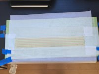
1) Conductor cut out on the cutting mat, waste paper and foil removed, non-stick paper in place
2) Stretch wrap pieces in place on top of non-stick paper (you can see the shiny surface of the stretch wrap)
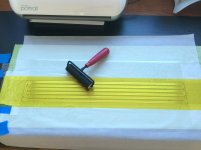
3) Kapton tape in place on top of conductor and stretch wrap
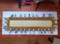
4) Resulting diaphragm in place in a frame, with clamps to allow tension adjustment. Masking tape works better for the stretching.
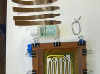
5) Preparing for the nerve-wracking job of soldering copper tape to the aluminum conductors. Not my favorite part of the process. A drop of flux is visible on each of the four connection points on the aluminum traces (two for the midrange, two for the tweeter).
2) Stretch wrap pieces in place on top of non-stick paper (you can see the shiny surface of the stretch wrap)
3) Kapton tape in place on top of conductor and stretch wrap
4) Resulting diaphragm in place in a frame, with clamps to allow tension adjustment. Masking tape works better for the stretching.
5) Preparing for the nerve-wracking job of soldering copper tape to the aluminum conductors. Not my favorite part of the process. A drop of flux is visible on each of the four connection points on the aluminum traces (two for the midrange, two for the tweeter).
Few
Attachments

Last edited:
Wesayso:
Things are trickier in the farfield, as you know so well. I'm still working out the details there. I can make the planar output look nice at one mic height and distance from the speakers but it doesn't take much mic movement (horizontally or vertically) for things to look less pretty. I've started focusing on the step response as a way to monitor what I'm doing. It seems to make it clearest how the sounds from the different points along the tower are adding together.
My crossover to the woofers is around 200 Hz and I don't have a way to delay video to compensate for latency, so I'm not sure I'll be able to use FIR to fix the phase response down there. I've started reading up on non-FIR ways to get crossovers that don't mangle transients but I need to learn more. I'm pleased that above 200 Hz it seems to act as a single full-range driver with no nasty phase anomalies to contend with.
I think the direct side wall reflections aren't a big problem but the case where the sound first hits the wall behind the speaker, then the side wall, and then aims at the listener, can be a problem . At least that's the case with a lot of toe-in. I've not really even begun to experiment with toe-in so I'm hoping I can firm up the image with some fiddling. I'm not going to be free to add a bunch of room treatment after intruding so much into the living room already, so getting rid of problematic reflections will require some creativity and patience. Maybe just pulling the speakers away from the wall behind them when I'm doing serious listening will be the most practical solution. I need to make the woofer towers easier to move. They weigh a ton and a half and I didn't design in any handles! I may install some Hudson bearings beneath the woofer bases so I can move them easier.
Few
Nice few !! Thanks!! about rolling out you can wet a glass plate to aply the kapton sticky side up, use a rubber roller with some water and a drop of dish soda. It will not stick to the kapton. Btw I noticed with the same kapton you used that resonance is pretty low as is ,because of the acrylic soft adhesive or maybe it is silicon still the same result 🙂 very nice project ,and I wonder if you could drop even lower 40 is pretty low for such small panels nicejob!!! Also cool to see you can reach 20khz almost, did you use any eq at the high end ? I had troubles reaching 20khz with the same adhesive kapton. 🙁 and no eq.
I am really curious about the difference about the soft foil surround an without, I might test it once 1vs1 🙂 keep up the nice work enjoying it!
I am really curious about the difference about the soft foil surround an without, I might test it once 1vs1 🙂 keep up the nice work enjoying it!
Last edited:

Wesayso:
Things are trickier in the farfield, as you know so well. I'm still working out the details there. I can make the planar output look nice at one mic height and distance from the speakers but it doesn't take much mic movement (horizontally or vertically) for things to look less pretty. I've started focusing on the step response as a way to monitor what I'm doing. It seems to make it clearest how the sounds from the different points along the tower are adding together.
My crossover to the woofers is around 200 Hz and I don't have a way to delay video to compensate for latency, so I'm not sure I'll be able to use FIR to fix the phase response down there. I've started reading up on non-FIR ways to get crossovers that don't mangle transients but I need to learn more. I'm pleased that above 200 Hz it seems to act as a single full-range driver with no nasty phase anomalies to contend with.
I think the direct side wall reflections aren't a big problem but the case where the sound first hits the wall behind the speaker, then the side wall, and then aims at the listener, can be a problem . At least that's the case with a lot of toe-in. I've not really even begun to experiment with toe-in so I'm hoping I can firm up the image with some fiddling. I'm not going to be free to add a bunch of room treatment after intruding so much into the living room already, so getting rid of problematic reflections will require some creativity and patience. Maybe just pulling the speakers away from the wall behind them when I'm doing serious listening will be the most practical solution. I need to make the woofer towers easier to move. They weigh a ton and a half and I didn't design in any handles! I may install some Hudson bearings beneath the woofer bases so I can move them easier.
Few
Faboulous job. Very impressive. I think you need need to talk to Uli and try Acourate for phase (a mix of linear and minimum) for woofer delay. I'll bet an email to him would be very helpful.
I don't build anything unless it looks good and professionally built, and you have achieved that!
Thanks for the tip, WrineX. I knew of the soap and water trick but it didn't occur to me to try it. The hard part for me was getting the kapton off the roll without tearing it. I found rolling it like a wheel after taping down the free end was the best method.
I agree the adhesive on the Kapton does a good job damping it so it's less rattly than I expected before I had it in hand. The adhesive is also stuck between the aluminum (which covers much of the surface) and the kapton so it serves as a constrained layer.
I still wanted to make it easier to stretch the Kapton, though, and I wanted some undriven diaphragm between the conductor and the attachment point. So I used the surround to add to the diaphragm's width (and increase its excursion range), provide a non-reflective mounting scheme, and lower the resonance.
I don't have a truly calibrated mic so I can't say with confidence what happens at 20 KHz. There is certainly some response up there even without equalization but I think the response starts to drop in the 18-20 KHz region. Can't say with confidence without a calibrated mic but I can certainly say the speakers work without equalization at frequencies beyond what I can hear! Still, I share your interest in wide bandwidth. Even if I can't hear a continuous 20 KHz tone I don't know whether I can perceive the slow rise time that comes with limited high frequency response.
Thanks for the kind words, ggetzoff. I'm now glad I invested the time and sweat to get a nice finish and a design I don't mind having in my living room. There were times during the construction when I wondered whether I might be going off the rails. What if they look pretty and sound like crap?! Thankfully, even though I have more refining to do I'm very pleased with the sound. I'll have to look into the Uli reference to fully appreciate the suggestion but thanks for the advice. I'll take a look.
Few
Damned ignore the roller few since i read ove the fact you drop the kapton on it Jesus I have some short memory issues , I'm sick so might be that. But anyhow very nice project and like the fact you really take the time in replies !!
What I did as wel is stick the kapton to a frame unroll it stick it to the other side tune it and drop it over, don't use a roller to get rid of the Bubbles I noticed where ever it touches it ducks up 🙂 a piece of toilet paper folded to a small piece worked best for me 🙂 kind of the same technique you used. But sharing makes every one smarter 🙂
What I did as wel is stick the kapton to a frame unroll it stick it to the other side tune it and drop it over, don't use a roller to get rid of the Bubbles I noticed where ever it touches it ducks up 🙂 a piece of toilet paper folded to a small piece worked best for me 🙂 kind of the same technique you used. But sharing makes every one smarter 🙂
Last edited:
One last thing you don't have a rise and peak from low to high is this eq ? Or the damping of the kapton ? I alway had a peak at the maximum frequency 15-18khz
This
Could be gone after adding multiple panels as I think of it
This
Could be gone after adding multiple panels as I think of it
Sorry to hear you're sick, WrineX. The viruses seem to span the globe---lots of sick folks way over here as well.
I'm happy to reply to folks; I relied on a lot of other peoples' posts when thinking, designing, building, testing...so the least I can do is try to pay back a bit.
Regarding peaks at high frequencies: Looking back at my earliest posts, before I had applied the midrange filter or added felt to the frames, I don't see much sign of peaking in the 15-18 KHz range.
When reporting on what I see in the measurements I feel compelled to add some context. What I see in the farfield depends strongly on measuring technique and mic position. If I use an n-cycle window (n = 4 <-> 15) and do a frequency scan then I need to measure in a few neighboring locations to discern the overall trend. I can refine the response at one mic position but in so doing I may actually be making the response worse 25 cm to the right or down. The bottom line is that I constantly have to remind myself not to fiddle with every little peak or dip with the mic at one spot, even if I've applied a window to the impulse response.
I've found the moving mic technique very helpful for seeing the broad trends, without all the complicated and very localized interference effects mucking up the works. When I use that approach the response of the planar towers peaks at 1 KHz and drops smoothly above and below that frequency. I should be careful, though, because the last time I made those measurements I first equalized the nearfield response to make it flat, and then used the moving mic technique in the farfield. When I did that the response dropped smoothly above and below 1 KHz.
I should add that the moving mic technique provides no phase information, unfortunately, so that limits its utility for some purposes. On the other hand, the planars seem to be pretty much minimum phase devices over the range I use them, even with the Bessel low-pass filter on the midrange conductor. To the extent that that's true, I should be able to extract the phase directly from the magnitude response, which I can measure using the moving mic technique. Preliminary results with this approach seem to work pretty well although I need to look into it far more extensively before I'd want to stake my reputation (do I have one?) on it.
Few
Wesayso:
Things are trickier in the farfield, as you know so well. I'm still working out the details there. I can make the planar output look nice at one mic height and distance from the speakers but it doesn't take much mic movement (horizontally or vertically) for things to look less pretty. I've started focusing on the step response as a way to monitor what I'm doing. It seems to make it clearest how the sounds from the different points along the tower are adding together.
My crossover to the woofers is around 200 Hz and I don't have a way to delay video to compensate for latency, so I'm not sure I'll be able to use FIR to fix the phase response down there. I've started reading up on non-FIR ways to get crossovers that don't mangle transients but I need to learn more. I'm pleased that above 200 Hz it seems to act as a single full-range driver with no nasty phase anomalies to contend with.
I think the direct side wall reflections aren't a big problem but the case where the sound first hits the wall behind the speaker, then the side wall, and then aims at the listener, can be a problem . At least that's the case with a lot of toe-in. I've not really even begun to experiment with toe-in so I'm hoping I can firm up the image with some fiddling. I'm not going to be free to add a bunch of room treatment after intruding so much into the living room already, so getting rid of problematic reflections will require some creativity and patience. Maybe just pulling the speakers away from the wall behind them when I'm doing serious listening will be the most practical solution. I need to make the woofer towers easier to move. They weigh a ton and a half and I didn't design in any handles! I may install some Hudson bearings beneath the woofer bases so I can move them easier.
Few
Uli's website: http://www.audiovero.de/en/acourate.php
Few,
Instead of using the sweeping mic to average at the listening position, you might want to try the method as proposed here:
http://www.diyaudio.com/forums/multi-way/221434-rephase-loudspeaker-phase-linearization-eq-fir-filtering-tool-141.html#post4920173
There's a few posts covering that method if you look for it. Some kind of methodology to do the averaging might be needed not to let a single measured point weigh in stronger than the rest.
Mitch posted another variation on that theme that might work too.
Keep your eye on the impulse (and filtered IR). You'll be able to see the reflections in each measurement, if using the above method it might be easier to connect it to certain walls etc. as you'll have more data connected to several microphone positions. The averaging will show the speaker output a lot cleaner (compared to the reflections) and contrary to the sweeping mic you'll have more data to analyse.
Ah yeah and phase changes strongly up high to. 1.8 cm to change 20 khz so not much to correct above 1K i believe 🙂
If these planar magnetic drivers behave anything like DMLs (thanks for the acronym clarification) then I've truly missed my target.
They do not. DML has wide dispersion, planars don't.
Planars are driven over the whole plane, a DML often in 1 point.
They are flat and emit sound. Thats what they have on common - their working are very different.
//
ggetzoff: Thanks for the links. I'll definitely take a look at Uli's site. I may hold off on a calibrated mic for now. I'm guessing mine has deviations mostly at the highest frequencies and those concern me the least. On the other hand, if someone thinks the generic Behringer calibration curve I downloaded is likely to be dramatically off, I'd definitely like to hear about it.
Wesayso: I've read a bunch of that thread but in bits and pieces while I had slowly developing experience to inform my reading. I'll take another look. I'm sure some of what I'm seeing is from reflections but I think some of it may be inherent in the summing of the signals from different parts of the speaker. On the one hand the diaphragms are continuous, on the other hand there are three gaps separating the four drivers. I'm wondering how much those gaps are complicating my results.
TNT: Thanks for reinforcing the point I was trying to make. I'm not sure I agree about the directivity, though. Certainly many planars beam but I've taken pains to avoid that with this design.
Few
Wesayso---I just looked again at the rePhase thread. I have indeed been using that technique and I've found it helpful. I'm doing it with REW and finding the summing of measurements to be very awkward, though. Unless I'm missing a feature, you have to do all the sums two at a time. And then sum some sums, and then repeat until you've included them all. I'd really love to be able to take ten measurements, select them all, and have them averaged. Is there a simple way to do that in REW? Am I just being dense?
I suppose I could export all the measurements and sum them in Matlab, but while in the middle of a measurement session I'd rather not have to bounce around between programs.
Few
I suppose I could export all the measurements and sum them in Matlab, but while in the middle of a measurement session I'd rather not have to bounce around between programs.
Few
ggetzoff: Acourate looks like good stuff. Too bad it costs as much as the miniDSP hardware I've invested in already. For a variety of reasons, including making sure my better half can live with the system, I've gone the dedicated hardware approach. I'll need to stick with that for this project, but I do remain interested in other methods for the long haul. I really have a soft spot for doing a lot for less money, so the Raspberry Pi stuff is intriguing as a side project. I realize it won't run Acourate, though.
Also, I don't have a way to fix the latency problems I'll have with video if I do heavy FIR audio filtering. My system needs to work as a sound source for TV/movies, again without requiring others to deal with inconveniences. I'm trying to integrate this into the life of someone who just wants to pick up the remote and listen to music or watch something on the screen. Quite the balancing act.
So I'm interested in exploring minimum phase approaches to crossovers that retain some semblance of the ability to reproduce an impulse/square wave...
Few
P.S. Your avatar is keeping me up at night! I can hear his whispering voice ringing in my head from years ago. "In your world..."
Wesayso---I just looked again at the rePhase thread. I have indeed been using that technique and I've found it helpful. I'm doing it with REW and finding the summing of measurements to be very awkward, though. Unless I'm missing a feature, you have to do all the sums two at a time. And then sum some sums, and then repeat until you've included them all. I'd really love to be able to take ten measurements, select them all, and have them averaged. Is there a simple way to do that in REW? Am I just being dense?
I suppose I could export all the measurements and sum them in Matlab, but while in the middle of a measurement session I'd rather not have to bounce around between programs.
Few
It's worth the trouble to sum them 2 at a time as you keep more usable data that way. If you just average 10 measurements (easy in REW) you loose the phase again. It's very easy (in SPL tab just choose 2 at a time and sum them (A+B/2). How long could that take? Just make sure is that all measurements have the IR aligned with their peak at zero.
I pointed at that summing process to get you a clearer view of your average speaker outcome. It would be worth it compared to the sweeping mic method.
In my opinion it's way easier to do this compared to your earlier ground level measurements. One way or another you'll need to look at what really happens at the listening spot. Especially with arrays and probably even more of a requirement with open baffle. You need a clear view of what happens at that distance in summing and the transition from the panels to the woofer array.
Personally I run a PC with JRiver for all things audio and video and that makes me able to re-align audio/video sync. For processing I use REW, JRiver and DRC-FIR. Acourate is similar to DRC-FIR (free) and Audiolense (paid software) would be yet another alternative.
RePhase could be a way to let you use short FIR corrections with minimal delay. For example only correcting the phase at your crossover with the least amount of tabs. But you don't need to take that step yet. Just look at what happens at the listening position first.
I want to be sure I'm not missing something with REW. I've found two ways to average, the "average the responses" button in the bottom left corner of the "all spl" tab, and then the A+B option under the controls of the "all spl" tab. Doing it the first way loses the phase for some reason. Why should that have to happen?
To do it with A+B, if I have 6 measurements to average, I first make the 6 measurements and then compute
1) 1 + 2
2) 3 + 4
3) 5 + 6
which creates three sums, sum(1,2), sum(3,4), and sum(5,6). Then I've summed the sums, but again it has to be just two at a time:
4) sum(1,2) + sum(3,4) = sum(1,2,3,4)
5) sum(1,2,3,4) + sum(5,6)
At that point I have all six summed and I adjust the vertical displacement to compensate for all the sums.
Am I doing this stupidly? It sure seems unnecessarily cumbersome to me. Why does the "average the responses" not retain the phase?
Few
- Home
- Loudspeakers
- Planars & Exotics
- DIY planar magnetic + open baffle woofer array