Dear Audiogods,
after some reading I have decided to embark on my first active 3-way xover build and I'll be etching my own pcb's.
I dug into a few of Rod Elliott's projects and bought a bunch of NE5532 Op-Amps and a 15-0-15v transformer. The rest still has to be decided but it will be used for both hifi and small PA systems. Initially unbalanced inputs, then if it works and it makes sense I might consider improving.
I like the fact that a 24dB LR is in phase but I would like to have some flexibility regarding xover point. I read this is difficult as many R's would need to change.
If I decide that a variable xover is what I care most about I'd need to chose a 12dB filter that is easier to implement, the down side is phase shift.
1) CHOSING A SLOPE
Case A, Rod Elliott's 24dB LR: the only easy way of having "variable" a 24dB network I can think of is building multiple separate circuits with a fixed frequency, and have a switch to change between them (although not practical as I'd need X amount of opamps, R and C's for every passband. It would work but seems like a stupid and wasteful solution)
Case B, Rod Elliott's variable 12dB: Variable 12dB means it has one output that is 180° out of phase so it needs to be inverted. How does this work in the case of a 3 way filter to be in phase? Would it need to have Mid switched 180° compared to the Low, and then the High switched 180° compared to the mid Which ultimately has low and high in phase with each other? Or did I miss something?
In his project 148 he mentions a bandpass which is 90° out of phase with 6db rolloff which isn't very usable, does this refer to the midrange output I'm hoping to obtain? Or is it something different?
Ths article from linkwitzlab suggests NOT to use 12dB slopes at all though so I'm stuck and confused.
Any expert advice on how to get a 3 way crossover whith phase coherent outputs(regardless of the slopes used)?
2) HPF to cut out subsonics/protect woofers
If I wanted to add a 35Hz highpass to protect my subs how does this translate to the schematic? Is it an additional Opamp controlling this?
Ultimately what I'm asking is not critical as my main goal here is to build something that works and sounds ok (so I'm happy to go with either of the preexisting circuits, then eventually I'll increase circuit complexity as I learn more about electronics) but these are the two big doubts I haven't found an answer to.
Thank you to anyone taking the time to babysit me!!
You are bound to get lots of comments that instead of designing a theoretically correct filter and then somehow getting aberrations caused by driver imperfections under control, you should just throw together a random filter and use numerical optimization to get the acoustical response right. You always get those when you ask any question about crossovers.
Anyway, theoretically you need to add a Butterworth all-pass filter of half the order when you want to make a third-order Linkwitz-Riley crossover, like this:

Its purpose is to ensure that the upper path gets the same phase shift (give or take 180 degrees) as the bottom two paths. An nth order Butterworth all-pass filter has the same phase shift as a 2nth order Linkwitz-Riley filter with the same corner frequency (give or take 180 degrees).
When you use an even order that is not a multiple of four, such as 2nd order, 12 dB/octave, the mid channel is out of phase with the others and needs to be inverted, like you already figured out. High and low are in phase.
Regarding an auxiliary high-pass to get rid of subsonics, I think you can best put it in front of the whole thing.
Anyway, theoretically you need to add a Butterworth all-pass filter of half the order when you want to make a third-order Linkwitz-Riley crossover, like this:
Its purpose is to ensure that the upper path gets the same phase shift (give or take 180 degrees) as the bottom two paths. An nth order Butterworth all-pass filter has the same phase shift as a 2nth order Linkwitz-Riley filter with the same corner frequency (give or take 180 degrees).
When you use an even order that is not a multiple of four, such as 2nd order, 12 dB/octave, the mid channel is out of phase with the others and needs to be inverted, like you already figured out. High and low are in phase.
Regarding an auxiliary high-pass to get rid of subsonics, I think you can best put it in front of the whole thing.

It has been said a million times before and I will say it again more: for proper functioning of any (multiway) loudspeaker crossover, the individual SPL characteristics of the speakers (=drivers) used must be taken into consideration. It is all about the combi of so called transfer functions both filter and driver.
All the wonderfull qualities of the electric part of the filter vanish into thin air once the filter is combined with a real loudspeaker. At the end of the day the acoustic output is al that matters, so the speaker plus filter must be jointly taken into consideration.
All the wonderfull qualities of the electric part of the filter vanish into thin air once the filter is combined with a real loudspeaker. At the end of the day the acoustic output is al that matters, so the speaker plus filter must be jointly taken into consideration.
I have analyzed and built a 4th order State Variable Linkwitz Riley filter. The huge advantage is that one filter circuit provides both lo-pass and hi-pass. That is, by changing the frequency determining components on one filter you have both lo-pass and hi-pass changed. While the crossover is still perfect at -6dB.
It does not make the design frequency agile. Whatever you choose, you'll always have 4 or more components to change on a 4th order filter. However you can be creative with jumpers etc. Smart placement of 4 jumpers give you 16 possible crossover points.
The thread with all the files and documentation is here: https://www.diyaudio.com/community/...tz-riley-state-variable-active-filter.419530/
Hi,
You mention this is for PA.
Will bass, mid and tweeter be in separated boxes so you can move them back and forth for time aligment?
Yes to your question, you need to built your active crossover with a pot for each band in order to balance the SPL among the speakers.
During adjustments, you may have to choose the best polarity combination between bass/mid and mid/tweeter according to the phase conditions.
Keep bass with the correct polarity and change mid and/or tweeter to achieve the best response.
You will combine this adjustments with physical position of speakers, again let bass fixed and move mid and/or tweeter back and forth.
And remember that the crossover also changes phase depending on the type, slope and frequency cut you choose - so the adjustments combine everything.
You can play a bit here, a bit there.
Phase changes occur in the electrical domain (crossover), in the geometrical domain (relative position of each speaker to each other and to the listening position) and in the acoustic domain where the speaker changes the phase as frequency changes. When you listen to the final full range 3-way speaker, all this phase changes are combined (summed).
Don't get too focussed in milimetric crossover perfectness (0.5dB, 0.3dB etc) since this is only one domain where frequency response and phase changes.
In the other domains (geometric and acoustic), there are much wilder variations in magnitudes of 5, 7, 10dB and even more (positive and negative).
Think about the final resultant.
You can simplify all these interactions, by measuring the final result with a calibrated microphone using timed measurement (measurement will get each speaker distance to the mic in milimeters) - REW can do it in any PC with a sound card.
It's worth the money for a calibrated mic, since it cost less than US$100.00.
And finally, it is good to have an overall EQ - due to the quantity of components, it's better to buy one - at least a simple cheap stereo 31-band (idealy a parametric). It makes a lot of difference in the final result, since you can attenuate bass bumps, compensate irregularities of your speakers, improve room or open space issues etc.
What is needed in the first place are measurements of the drivers in the box. For that you need measurments by others or measurement gear. The neasurements usually come in .zma format files for impedance (not needed for active) and in box SPL measurements of the drivers involved in .frd or .txt format. Then you need to optimize the transfer functions of the filter in a simulator, which finally provides the correct (non standard!!) C and R component values in the active filter stages.
The background of all this is that an in box loudspeaker, say a 6,5"woofer, behaves very differently in a real box than when measured on a big AES baffle. Most manufacturers measure on on such baffles. To make things worse, most loudspekers do not quite behave as perfect ruler flat textbook like SPL devices.
There used to be some terrific step by step tutorials on the internet, but time fails me now to present one here. So the above is all a bit sketchy and thus a gross simplification...
This may get you started: http://audio.claub.net/software/DaveDalFarra/Simple Loudspeaker Design ver2.pdf
Although the tutorial is about passive x/o design, it will give you some basic insight in the various issues to be taken into consideration.
Although the tutorial is about passive x/o design, it will give you some basic insight in the various issues to be taken into consideration.
@ron68 yes the idea is to have 3 separate speaker enclosures.
I will probably make a 24db L-R crossover since it is should reduce phase issues
@Boden thanks for the link! So what you are saying is that to have an active xover that is properly made the transfer function determines the ideal R C values to use for that frequency and speaker? Because putting different values in the calculator one could get any amount of combinations and I had been thinking how it is that one decides what to go with.
It basically has to be tailored specifically for those specific drivers in those specific boxes for it to sound great? and will just sound normal if used for any other generic speaker?
I'll probably give up on the variable xover points for now... while it would be beautiful I'm a novice and being too ambitious won't help much for the moment..
Doubt on how to integrate the buffer stage on the outputs to have volume control:
Do I omit the 100 Ohm resistor in the crossover output and add the buffer stage after it? Or do the 100R output resistors stay there in both parts of the circuit?
Does it also mean I have to effectively add another 3 Opamps to the project?
It is not a matter of "normal", but simply off: the drivers' individual acoustic outputs will not sum properly, leading to non-flat erraticand will just sound normal if used for any other generic speaker?
system response.It basically has to be tailored specifically for those specific drivers in those specific boxes for it to sound great?
Yes, but it is not about sounding great, but being acoustically correct. See above. In somewhat simplified terms, it is a matter of right and wrong. That being said, a lot of people here even in 2025 do not measure, do not simulate do not optimize, but simply think their ears can do the multiway x/o design job. Not.
If You want some more insight, Analog has some books that might be of interest, like this one :
https://www.analog.com/en/resources/technical-books/linear-circuit-design-handbook.html
- Linkwitz-Riley is series-connected Butterworth. Normal Butterworth has Q=0.707 so two of them in series will give a Q=0.5 for a near perfect (electrical) impulse response.
https://www.analog.com/en/resources/technical-books/linear-circuit-design-handbook.html
- Linkwitz-Riley is series-connected Butterworth. Normal Butterworth has Q=0.707 so two of them in series will give a Q=0.5 for a near perfect (electrical) impulse response.
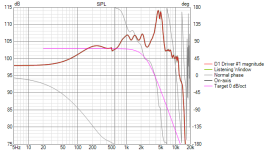
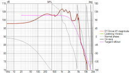
To illustrate the point: attached are two graphs of a real, rather difficult midwoofer in a box, heavily breaking up at around 5 kHz and also showing the infamous Baffle Step.
The purple line shows a textbook BUT2 lowpass transfer function. TRhe second pictures demonstrates what happens if the -nightmare- real driver is filtered by our textbook BUT2 electrical filter.
The resulting driver output is nowhere near the ideal purple line, but all over the place, requiring a number of additional correcting network elements to turn the acoustic ouput into something half decent.. I did not even try to go there.
Attachments
I guess I should have put it into more context. I have a JBL- Urei 5235. Its a crossover with replaceable pcb's so you can decide xover frequency and slope. Since it's a generic off the shelf product would this (and every other non-custom xover on the market) have the summing and response issues you mention?It is not a matter of "normal", but simply off: the drivers' individual acoustic outputs will not sum properly, leading to non-flat erratic
system response.
Yes, but it is not about sounding great, but being acoustically correct. See above. In somewhat simplified terms, it is a matter of right and wrong. That being said, a lot of people here even in 2025 do not measure, do not simulate do not optimize, but simply think their ears can do the multiway x/o design job. Not.
The traditional approach is to use drivers that have a reasonable response to about two octaves beyond the crossover frequency and to use a reasonably steep crossover filter that has its outputs in phase, like a Linkwitz-Riley filter has. Then measure the phase difference between the drivers around the crossover frequencies to determine what polarity will work best and connect them accordingly. It worked well enough for everyone until computers became too cheap, now you have to use numerical optimization techniques or be prepared to justify yourself.
The answer is: yes. Only in very rare cases will drivers and filter fit.would this (and every other non-custom xover on the market) have the summing and response issues you mention?
Understood, thanks for the insight!
Well for now I think I will just stick with "random" values simply because I don't want to overcomplicate things. I mainly want to play around with etching my own PCB and be able to have a 3 way system. Then when that i working I will think about perfectly matching components as the circuit doesn't really change.
If in the schematic provided I want to add a volume control buffer stage, do I remove 100R between the two circuits? or is one per stage needed and i simply connect them together?
- Home
- Source & Line
- Analog Line Level
- DIY newbie: variable 3-way 12 or 24dB LR crossover build