"Good frequency response, no ugly dipole peak allowed" from the first post.
Polar plots are something of a visual delusion. There are no "red lines" for speaker sound like a polar plot, just loosey-goosey power spectra.
What gets to your ears from speakers bounces around the room a few times, and twice the bounce for dipoles. What you hear is a perceptual construction and if the sound of some harmonic is a bit diminished (if your head is absolutely stationary all the time), the sound barely changes at all.
Features of the room (and/or the exact placement of your head) will derange the frequency response at your ears a whole lot more than beam-formation by the driver. And you can alter the room in various ways but you can't improve much the room influence except by damping to the point of harming the sound of music.
Anybody can try this experiment right now: rotate one speaker/cabinet part of a turn.
B.
Last edited:
I had planned to do some more measurements with the EPDM suspension but there were 2 problems:
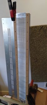
First, when I don't have a solid alu backing but rather a segmented membrane, then, unless I can apply some tension when corrugating the membrane will not corrugate nice and parallel but gets skewed.
On the left of the membrane, the corrugations are not nicely parallel.


The problem appears when I can't apply any tension to the membrane in the corrugator, which is when the membrane edge is short enough that it disappears into the red funnel.
One option would be to reduce the length of this funnel, red in the image.

Another or maybe complementary solution is to work around the issue by just making the membrane longer. Say if I add ~ 10 cm membrane length of solid aluminum backing and then just cut it off afterwards. This is probably the easiest solution. since the funnel length still helps in keeping the corrugations parallel.

And now my second problem, when mounting a membrane with the EPDM rubber suspension, there is definently buckling. I think the EPDM suspension requires a solid aluminum backing, those membranes still work great but without it I get problems like this:


I still want to try some more with the EPDM suspension, because it is so easy to cut and apply, and the low frequency boost is nice. But I also want to coaxially drive my membrane, since it improves the top end response by a lot. So for the next weekend, I want to see if I can make coaxially driven coils work with a solid backing like this:

Or if the solid backing makes both coils act as one and thus negate the coaxiial thing.
If that does not work, then I will probably abandon the EPDM rubber suspension for good, or at least until I get some new idea for how to get good high frequency dispersion without dips.
First, when I don't have a solid alu backing but rather a segmented membrane, then, unless I can apply some tension when corrugating the membrane will not corrugate nice and parallel but gets skewed.
On the left of the membrane, the corrugations are not nicely parallel.
The problem appears when I can't apply any tension to the membrane in the corrugator, which is when the membrane edge is short enough that it disappears into the red funnel.
One option would be to reduce the length of this funnel, red in the image.
Another or maybe complementary solution is to work around the issue by just making the membrane longer. Say if I add ~ 10 cm membrane length of solid aluminum backing and then just cut it off afterwards. This is probably the easiest solution. since the funnel length still helps in keeping the corrugations parallel.
And now my second problem, when mounting a membrane with the EPDM rubber suspension, there is definently buckling. I think the EPDM suspension requires a solid aluminum backing, those membranes still work great but without it I get problems like this:
I still want to try some more with the EPDM suspension, because it is so easy to cut and apply, and the low frequency boost is nice. But I also want to coaxially drive my membrane, since it improves the top end response by a lot. So for the next weekend, I want to see if I can make coaxially driven coils work with a solid backing like this:
Or if the solid backing makes both coils act as one and thus negate the coaxiial thing.
If that does not work, then I will probably abandon the EPDM rubber suspension for good, or at least until I get some new idea for how to get good high frequency dispersion without dips.
Last edited:
If you are nearby Hägersten (Västbergavägen 19, Hägersten), perhaps a visit to Kuntze & Co can help you/us.
If you are nearby Hägersten (Västbergavägen 19, Hägersten), perhaps a visit to Kuntze & Co can help you/us.
It's not that close, but not that far away since I live centrally in Stockholm. As far as I can see they only stock closed cell rubber, where I believe that open cell foam / EPDM rubber would probably be a better fit. Open cell EPDM, while it does seem to exist does not look to be as commonly available, I only find "ask us for a quote" which sounds expensive.
And I have more data on EPDM & foam coaxial membranes. Lost of individual measurements but the conclusion can be summarized as:
- A solid backing membrane can in fact be coaxially driven in the 10-20 khz range, which is cool.
- EPDM suspension is more efficient on the low end, but has sharp peaks and dips on the top end (5-20 khz). And coaxially driving the membrane is no silver bullet in fixing those peaks and dips. I can mitigate them, but then other problems creep up and all in all it goes against my goal of needing as little EQ as possible. And since coaxial coils does not let me fix the response of EPDM suspended membranes, this is another nail in the coffin for the EPDM.
- Coaxial coils again, works just fine. In fact 8 khz LR2 lowpass on the outer coil with an 8 khz single order all pass on the inner coil works great. But while it works, the response is still pretty good even without coaxial coils as long as I have yarn in the outer holes, so I'm not sure if it is worth the added complexity.
This setup, the white 90 degree is messed up because the mini waveguides is only on the front instead of symmetrical but the off axis dispersion is great up until 12 khz, and there are no sharp peaks or dips anywhere. This is good enough for my desired use case, so I am leaning towards settling with this and abandoning coaixial coils, at least for this specific driver and set of goals.
Another benefit of not having coaxially driven coils is that then I can run coils on both sides of the membrane, which greatly simplifies the shading network. With dual sided dual trace coils then I have 4 coils in total that I can play around with and terminate early, thus bringing the level down to -6 dB until I have to get fancy and add parallel resistors in the membrane. With only a single side then I can only get down to -3 dB and thus need to add parallel resistors earlier, which requires the early resistors to have lower resistance, which makes them harder to manifacture.
Here is an example with 4 coils, which is roughly equivalent to what I can do with 2 sides of coils with 2 traces in each.
EPDM suspension:
Foam suspension:
Did you only try the P profile for EPDM. EPDM itself should be a superior material as I understand it - maybe it's the profile? Perhaps "solid" EPDM would be better?
//
//
Did you only try the P profile for EPDM. EPDM itself should be a superior material as I understand it - maybe it's the profile? Perhaps "solid" EPDM would be better?
Exaclty, I only tried the P-profile although since I cut away some of it it became more of a D profile like this:
But in the end it is too stiff. I believe it would perform better if the walls were thinner, or probably even better if as you say it is solid. But for solid EPDM to work it would need to be open cell foam and not closed cell foam like these profiles.

That's a lot of measurements to digest. But is it really necessary to include the dispersions when comparing different surround materials?
I mean, the dispersion should be more or less the same as the apperture and the speaker's surface are the same?
If not the membrane will have different distances to the front plate that is affecting the Helmholtz' Resonator frequency.
If you make some overlays with just the SPL for the different materials at 0°, I think it would be easier to evaluate the results.
At least for starters anyway.
So the EPDM has good low frequency properties but not high frequency?
I think we need to ask us why enough times to get to the bottom and find the solution.
First why:
Why does the surround affect the high frequency response? The Xmax needed should be enough for just any "spongy" material.
Last edited:
So the EPDM has good low frequency properties but not high frequency?
I think we need to ask us why enough times to get to the bottom and find the solution.
First why:
Why does the surround affect the high frequency response? The Xmax needed should be enough for just any "spongy" material.
To, me, it makes sense that the surround affects the high frequency response.
The loose white foam is so soft and loose that I believe it is roughly comparable to having the membrane suspended in free air.
The EPDM rubber, however, is quite stiff. I believe that the EPDM is so stiff that it dampens the membrane, thus a lot of force that could be used to generate sound instead propagates in the suspension thus generating less sound.
Nice work !!!!
i was using this. i compared pp to single ended and .. thought about a method without having to use 2 foams.. since we both know they act weird.. sometimes the foils ends up closer to the magnets then other panels... ill try to make a exact replica of the PP version but single ended see how it 1:1 works. who knows 🙂
i was using this. i compared pp to single ended and .. thought about a method without having to use 2 foams.. since we both know they act weird.. sometimes the foils ends up closer to the magnets then other panels... ill try to make a exact replica of the PP version but single ended see how it 1:1 works. who knows 🙂
It seems very, very, roughly IMOThe loose white foam is so soft and loose that I believe it is roughly comparable to having the membrane suspended in free air.
Nice work !!!!
i was using this. i compared pp to single ended and .. thought about a method without having to use 2 foams.. since we both know they act weird.. sometimes the foils ends up closer to the magnets then other panels... ill try to make a exact replica of the PP version but single ended see how it 1:1 works. who knows 🙂
Your video got me to try out single ended again. And like you measured, it is smoother but there is not a huge difference. The google drive sync seems to have had a hiccup so we'll have to wait until tomorrow to get the measurements.
But it is 6 dB less efficient, yikes. I'd be reluctantly OK to loose 3 dB efficiency if it was perfectly smooth in exchange. But 6 dB less efficienct for a minor smoothness improvement mostly above 8 khz is not a trade I am OK with, or at least not with my current design goals so I will continue to run push pull.
And I have shamelessly stolen @solhaga s process of corrugating the foil where he tapes it onto another stiffer aluminum backing. It solves a problem where, if I have a membrane that is not solid but has gaps between the coil and the undriven fill, and I apply a lot of pressure to my corrugator by increasing the spring tension, then it no longer corrugates nice an parallel but the plain kapton parts gets squished to the middle. But with solhagas method this is no longer a problem.
The main benefit of his technique, is that it allows me to apply a lot more pressure when corrugating without issues, which also opens the door of using finer toothed cog wheels that have less deep but more corrugations. I tried my more fine toothed cog wheel and worked great, so during the week I plan to print 2 more cog wheels to try out even more corrugations.
Apart from playing around with the corrugations I an reviewing all my measurements to help me finalize the membrane setup. After some review I think my best configuration is the coaxial setup after all. The increased top end dispersion is nice but what I like the most is that it has a smooth off axis drop off. Look closely at the circled green region, with the coaxially driven membrane to the right, the directivity is smoothly falling from 8 khz and upwards. With the non coaxially driven membrane, the directivity blooms a bit such that 0, 15 and 30 degrees all have equal output @ 10 khz, and then fall off sharply above. I want that smoothness, so coaxial is probably the best way forward.
During next weekend I want to finalize what alu weights are suitable for a coaxial membrane. Should both coils be the same weight? Or should the inner coil be lighter?
I want to test:
- 50 um outer and inner coil
- 30 um outer and inner coil
- 50 um outer, 30 um inner coil
Nice !!! ill look up solhaga's idea, because i run into the same problem, and i would love to have less deep corrugations as well
about the efficiency it indeed should be 6 dB less efficient. it all depends on what you need it to be of course. but in reality i think its a little less then 6 db 4-5. ill make a single ended one with the exact same coil. see what that does. 1:1
about the efficiency it indeed should be 6 dB less efficient. it all depends on what you need it to be of course. but in reality i think its a little less then 6 db 4-5. ill make a single ended one with the exact same coil. see what that does. 1:1
Hmm since you are gone shade them i guess you need all output you can get so PP makes sense. but i dont see a 6 db gain. looks to be more 4-5
Here i made a single ended with the exact membrane as the pushpull, and cheap perf steel (to thin steel even 1mm + 50% open area, so output could be slightly higher i think) it acts as 0.5mm steel or less because of its open area
Pic 1 gated at +- 1 meter ignore the spl. blue push pull

And distortion, should have crossed it lower and use more output 🙁 so the differences would be more clear 🙁 no EQ used, aah well the difference in output and smoothness remain visible.
PP

Single

that metal thing was not used in the measurement.
.jpg")
.jpg")
The membrane with this sticky method looks to be having a higher resonance . so using 2 foams front and back gives a nice gentle damping then these sticky foams (i think because how soft the ones in the push pull are). might increase width of the foil see what that does. push pull also lowers resonance but not by 80hz i think 🙂
i think with the dept of corrugation you can also get a little more output and lower stiffness if needed. (more of the foil would be closer to the magnets in single ended). this should be less of a thing in push pull i guess ?
Here i made a single ended with the exact membrane as the pushpull, and cheap perf steel (to thin steel even 1mm + 50% open area, so output could be slightly higher i think) it acts as 0.5mm steel or less because of its open area
Pic 1 gated at +- 1 meter ignore the spl. blue push pull
And distortion, should have crossed it lower and use more output 🙁 so the differences would be more clear 🙁 no EQ used, aah well the difference in output and smoothness remain visible.
PP
Single
that metal thing was not used in the measurement.
The membrane with this sticky method looks to be having a higher resonance . so using 2 foams front and back gives a nice gentle damping then these sticky foams (i think because how soft the ones in the push pull are). might increase width of the foil see what that does. push pull also lowers resonance but not by 80hz i think 🙂
i think with the dept of corrugation you can also get a little more output and lower stiffness if needed. (more of the foil would be closer to the magnets in single ended). this should be less of a thing in push pull i guess ?
Attachments
Last edited:
Small question how wide are your foil between foams ? since i might have made mine to slim , i am not able to get as low res.
Solhaga and me where thinking about what the depth of the corrugation does to the resonance (either by using a different corrugator or streching out the foil more so the corrugation becomes less deep, this might run into troubles distortion wise). i think smaller depth means lower res ? less stiff like i beams... the higher they are the stiffer.. so its either one of the 2 less deep corrugation or wider foil i think (besides more soft foams, that will also decrease resonance)
Solhaga and me where thinking about what the depth of the corrugation does to the resonance (either by using a different corrugator or streching out the foil more so the corrugation becomes less deep, this might run into troubles distortion wise). i think smaller depth means lower res ? less stiff like i beams... the higher they are the stiffer.. so its either one of the 2 less deep corrugation or wider foil i think (besides more soft foams, that will also decrease resonance)
Simple question about corrugation. The electrical current flows vertically, but also from back to front, for example. Does this lead to slight lateral forces?
If you think of a ideal corrugation, like a square wave, the force on the part of the trace that goes in and out of the loudspeaker will move the membrane up and down. So two nearby sides will move like an AMT does.

If your left hand the first finger is the magnetic flux density and the second finger is current density, the force will be along your thumb.
That is in and out of your loudspeaker.
Or:
If you then pretend to follow the corrugation, you'll notice that the angle of the thumb will rock side ways, that is along the membrane.
I can imaging that the surround must be firm enough so it can mitigate the movements or be compliant enough so the movements doesn't result in any distortion. If the latter, the AMT motion will contibute to the sound waves.
ChatGPT says:
When the membrane is corrugated, it introduces mechanical geometry that converts the planar electromagnetic force into a combination of movements:
- Primary (desired) direction: The corrugated membrane still primarily moves perpendicular (forward and backward) relative to the plane formed by the magnet arrangement.
- Secondary (induced) directions: Due to the geometry of corrugations, as the membrane moves forward and backward, it also experiences local bending, causing some slight vertical ("up-and-down") deformation. This vertical deformation is not directly due to the electromagnetic force itself but is the mechanical consequence of applying a uniform perpendicular force on a corrugated geometry.
To illustrate more explicitly:
- Without corrugation: The membrane moves flatly and uniformly, purely in-and-out, assuming perfect rigidity.
- With corrugation: The membrane experiences local bending or folding as it moves. The corrugations flex or stretch slightly, resulting in secondary movements vertically or laterally within the corrugation structure itself. This mechanical deformation results in slight vertical (up-and-down) motions within each corrugation period.
Last edited:
I decided to try a solid aluminum backed membrane with coaxial coils & the soft white foam surround.
The solid backing is by far the easiest to produce and much stiffer than the other options, as long as it works good enough I am leaning towards using it by default.
And as luck would have it, it works pretty well. The first is where the outer coil has a first order low pass @ 8 khz. The second is a second order LR2 @ 8 khz + a first order all pass @ 8 khz for the inner coil + inverted signal.


EQ used for the inner coil:

The 0-60 response is pretty much perfect apart from lower output on the top end but that can be adjusted with some EQ. There is some more off axis response above 8 khz at 75-90 degrees but not that significant. And if I build symmetrical waveguides then I should be able to suppress that, which is the current plan since it will let me hide the woofers inside the waveguides.
Also, the improvement from first order to second order is there but maybe not that big of a deal. The first order would be very easy to run passive since I only need to add a parallel capacitor to the outer coil. The second order is a bit more complicated to run passive but not a problem if I run each coil active. But I like simple so I would prefer to cross the coaxial coils passively.
Also, this is with 12 um kapton with 12 um silicone adhesive and 14 um aluminum backing, the 30 um acrylic self adhesive aluminum for the coils. Next weekend I want to try the same but with 50 um self adhesive aluminum for the coils. Would also be interesting to try a lighter membrane, I do have some 6 um mylar lying around which is very floppy but should be strong enough if used with a solid aluminum backing.
The solid backing is by far the easiest to produce and much stiffer than the other options, as long as it works good enough I am leaning towards using it by default.
And as luck would have it, it works pretty well. The first is where the outer coil has a first order low pass @ 8 khz. The second is a second order LR2 @ 8 khz + a first order all pass @ 8 khz for the inner coil + inverted signal.
EQ used for the inner coil:
The 0-60 response is pretty much perfect apart from lower output on the top end but that can be adjusted with some EQ. There is some more off axis response above 8 khz at 75-90 degrees but not that significant. And if I build symmetrical waveguides then I should be able to suppress that, which is the current plan since it will let me hide the woofers inside the waveguides.
Also, the improvement from first order to second order is there but maybe not that big of a deal. The first order would be very easy to run passive since I only need to add a parallel capacitor to the outer coil. The second order is a bit more complicated to run passive but not a problem if I run each coil active. But I like simple so I would prefer to cross the coaxial coils passively.
Also, this is with 12 um kapton with 12 um silicone adhesive and 14 um aluminum backing, the 30 um acrylic self adhesive aluminum for the coils. Next weekend I want to try the same but with 50 um self adhesive aluminum for the coils. Would also be interesting to try a lighter membrane, I do have some 6 um mylar lying around which is very floppy but should be strong enough if used with a solid aluminum backing.
I diud a quick test with the 9/12 mylar same coils
one with regular 12 mylar only and one with the laminate.

Brown normal mylar green mylar al laminate as carrier.

Just Mylar and 15 micron al tape as coil

Same coil but with 9/12 mylar
res goes up as expected due to its stiffness. and top end loses a bit 🙁 and looks less smooth then the regular mylar one. but in you case you have les and less driven voice coil. it might add much more then it does in my versions. (it only takes away in my versions)
the rest is hard to say since resonance changed. maybe this combo is interesting for lower frequencies ? since res went up the distortion at res does not say much 🙁
you can have some meters no problem, not sure if i got 6 left.. its hard to say. i might need to ask UKI if they have some left overs we might be able to buy. i hate having none left 🙁
one with regular 12 mylar only and one with the laminate.
Brown normal mylar green mylar al laminate as carrier.
Just Mylar and 15 micron al tape as coil
Same coil but with 9/12 mylar
res goes up as expected due to its stiffness. and top end loses a bit 🙁 and looks less smooth then the regular mylar one. but in you case you have les and less driven voice coil. it might add much more then it does in my versions. (it only takes away in my versions)
the rest is hard to say since resonance changed. maybe this combo is interesting for lower frequencies ? since res went up the distortion at res does not say much 🙁
you can have some meters no problem, not sure if i got 6 left.. its hard to say. i might need to ask UKI if they have some left overs we might be able to buy. i hate having none left 🙁
Here is the things i did in a video. just for background. they where measured in a small baffle. and i used a 12db oct filter LR at 600 hz, i would never cross that low but wanted to have some of the resonance in there... should have going 24 db oct at 500 or something to drive the difference home more when i think of it. i thinnk it might be interesting in you setup, less in mine. the only problem i see is the loss of already lower top end above 15khz
Interesting test!Here is the things i did in a video. just for background. they where measured in a small baffle. and i used a 12db oct filter LR at 600 hz, i would never cross that low but wanted to have some of the resonance in there... should have going 24 db oct at 500 or something to drive the difference home more when i think of it. i thinnk it might be interesting in you setup, less in mine. the only problem i see is the loss of already lower top end above 15khz
But like you say in the video, I agree that in that tweeter where you cover pretty much all of the foil already with the self adhesive aluminum, adding extra aluminum doesn't make much sense and just adds weight since it is already stiff enough.
But all of this has made me want to try 4 different configurations,, all with 30 um self adhesive aluminum coils:
- A thinner mylar + alu composite, say 12 um mylar + 9 um alu instead of my current 12 um kapton (same weight as mylar) + 12 um silicone glue (which weighs as much as the 12 um kapton) + 14 um of aluminum.
- A slightly thicker mylar + alu composite (10 um mylar + 15 um alu)
- Just 12 um mylar, no backing aluminum and no undriven filled areas around the coils, so basically this but with 3 mm coils instead of 6 mm
To make the mylar a little stiffer, I want to try @solhaga s method of baking it in the oven at a low temperature to reset it to hold the corrugations instead of only relying on the aluminum.
I did try this before, however, and in that case there was a large dip on the top end. If I am very lucky then that dip is less of a problem with coaxially driven coils such that only the 2 inner rows are triven so high. But more realistically, I believe it to not be stiff enough and will probably have if not the same problem, some other problem.
- Same as above but with 23 um mylar, which should be a lot stiffer than 12 um. It will be especially interesting to compare this with composite membranes of similar weight, a 12 um mylar + 9 um aluminum would weigh pretty similar (the 23 um mylar would weigh 86% of the 9-12 composite.
In short, I want to answer the following question of assmuning I have enough film thickness to add the required stiffness for my driver, what material should the film be made of? Is it best to only have mylar, but make it thicker if more stiffness is needed? Or should it be a composite of say mylar + aluminum?
- Home
- Loudspeakers
- Planars & Exotics
- DIY midtweeter planar, physically curved and shaded to be used in a dipole CBT