Several micro Henry is small enough value - they could be even air-core if you want - it depends on task, construction, current, ets.
For that picture (that schematics) - quite often we take large type (2W-5W) resistors (R37, R41), and use them as inductor cores.
You can use some online calculator to calc turns number. You can chose between one layer winding and two (or multylayer) winding.
For example, for 12-14 mm resistor core it could be about 30-40 turns of wire - it's very approximately (I took numbers from 20-years ago memory).
Task is very easy if you have inductance meter (you can buy any cheap chinese one for this purpose), but if you don't have - it would be ok, if you'll have 6-8 uH real inductance (+-10..-+20% have to be ok).
Last edited:
If you dont't have a coil winder (there are reasonably cheap hand-crank one's on eBay), then a cordless drill can be used as a winder. I'd find a suitable cyindrical tube and wind excess turns, you can can measure inductance and remove turns to fine-tune the value that way, and it will be neat.
For high current audio inductors the windings should be supported to prevent vibration, so wind tightly on a former and apply a little superglue or lock the windings in place with epoxy or similar if an open coil. This will reduce the tendancy for them to "sing".
For high current audio inductors the windings should be supported to prevent vibration, so wind tightly on a former and apply a little superglue or lock the windings in place with epoxy or similar if an open coil. This will reduce the tendancy for them to "sing".
It is very strange the location of such chokes. In any case, which is said below, say, to make them over a resistor is a common task. take a piece of wire 0.5 to 1mm diameter (Enameled) and wire 10-12 turns over the specified resistor ans then solder the extremes to resistor wires.
Oh and a point I forgot, inductors will couple to each other if too close (especially if parallel, rotating one by 90 degrees will help).
But 10-12 turns will be less then 6.9 uH, I think? It will be about 2-3 uH, depends on resistor size.and wire 10-12 turns over the specified resistor
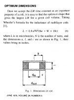
It also depends on wire diameter (Thinner wire has high inductance per turn than wide ones), coil diameter (Increasing diameter increase inductance non-linealy) turns space (closer has higher inductance than spaced), coil length, number of wire layers and core properties. As a first attempt, try the Wheeler (or Weeler, I am not sure) formula in any Radioamateur's handbook or in the web.
Last edited:
I find that the Wheeler inductance equations give very good estimates of the inductance of a hand wound DIY air core coil. This website implements the equations in a handy "calculator" format:
Inductance Calculation
After winding the coils you probably want to measure their inductance to be certain you got what you wanted. An excellent test instrument for making these measurements is the DER EE DE-5000
DER EE High Accuracy Handheld LCR Meter DE-5000 bundle TL-22 785533177862 | eBay
DER EE DE-5000 High Accuracy Handheld LCR Meter ONLY Metar New F/S | eBay
Thanks for all answers.
I have now a lot of informations on winding coils and tools.😎
"the strange location of such chokes" was extracted from a Quad405 circuit with symetrical 50V power supply.
- which wire diameter is safe ?
- For audio range, can special winding technics (bifilar...) or special wire (litz...) upgrade results (dynamic, distorsion...) ?
For audio frequencies I'd not be too worried about reducing losses, that's going to get important at higher frequencies where the skin-depth of copper becomes significantly less than the wire diameter. Distortion only happens if the core is magnetic, magnetic materials are non-linear, often strongly so. Air/plastic/ceramic are basically free-space and Maxwell's equations (which are linear) apply directly.
Last edited:
A. N. Thiele had an article in J.A.E.S. titled Air Cored Inductors for Audio. I made crossover coils with its calculation an it gave 1% result after checking with an accurate LCR meter.
No. Use just thick enough wire which can handle output currrent.- For audio range, can special winding technics (bifilar...) or special wire (litz...) upgrade results (dynamic, distorsion...) ?
A] I don't see any mention of wire diameter in the Wheeler equations (Inductance Calculation).It also depends on wire diameter (Thinner wire has high inductance per turn than wide ones
B] How does one calculate the amount of DC the coil will handle?
Thiele merely applied the appropriate formula that he found in Wheeler's 1928 paper. Thiele cites Wheeler's paper as his bibliographic reference [1]. Screen capture image from Thiele's AES paper, below.
Besides the wonderful web-based "calculator" linked in post #9 of this thread, there are a bunch of other websites that present and discuss Wheeler's formulas. Here are a couple nice ones:
Wheeler Formulas for inductance
http://www.thompsonrd.com/induct2.pdf
_
Besides the wonderful web-based "calculator" linked in post #9 of this thread, there are a bunch of other websites that present and discuss Wheeler's formulas. Here are a couple nice ones:
Wheeler Formulas for inductance
http://www.thompsonrd.com/induct2.pdf
_
Attachments
There are calculations for optimum dimentions, but if we use some definite core then inductor will be not optimal, but usually it is ok (just several turns more).
It's a pleasure when you ask a question to get so qualified answers 😎
For quad 405 (attachment #1), is 0,5mm wire size enough for coils ?
For quad 405 (attachment #1), is 0,5mm wire size enough for coils ?
Q:
A) Wheeler (And many other, see the Langford-Smith book) formula is an approximation. There is no exact formula for real world inductors because their inductance is affected by a multiplicity of factors;
Wikipedia comfirms my previous knowledge:
As a practical matter, longer wires have more inductance, and thicker wires have less, analogous to their electrical resistance (although the relationships aren't linear, and are different in kind from the relationships that length and diameter bear to resistance).
B) DC inductors without iron cores or with open magnetic circuit, are usually based in maximum resistance to DC, or sometimes, self rigidity to vibration and movements. In RF large copper diameters are used and in extreme cases, they are silver plated at UHF frequencies to reduce skin depth effects.
A:A] I don't see any mention of wire diameter in the Wheeler equations (Inductance Calculation).
B] How does one calculate the amount of DC the coil will handle?
A) Wheeler (And many other, see the Langford-Smith book) formula is an approximation. There is no exact formula for real world inductors because their inductance is affected by a multiplicity of factors;
Wikipedia comfirms my previous knowledge:
As a practical matter, longer wires have more inductance, and thicker wires have less, analogous to their electrical resistance (although the relationships aren't linear, and are different in kind from the relationships that length and diameter bear to resistance).
B) DC inductors without iron cores or with open magnetic circuit, are usually based in maximum resistance to DC, or sometimes, self rigidity to vibration and movements. In RF large copper diameters are used and in extreme cases, they are silver plated at UHF frequencies to reduce skin depth effects.
Last edited:
Wire diameter is not included in the Wheeler inductance formulae for multi-turn coils; because its effect is extremely small. The formulae are accurate to 1-2% even when neglecting wire diameter entirely. Thus the effects of wire diameter amount to less than 1-2% of the total inductance of a multi-turn coil. Wheeler, an engineer, considered it negligible. And he neglected it.
- Home
- Design & Build
- Parts
- DIY inductors ?